Contemporary Control Systems Modbus Cube I/O MR-AO4 User Manual
Page 2
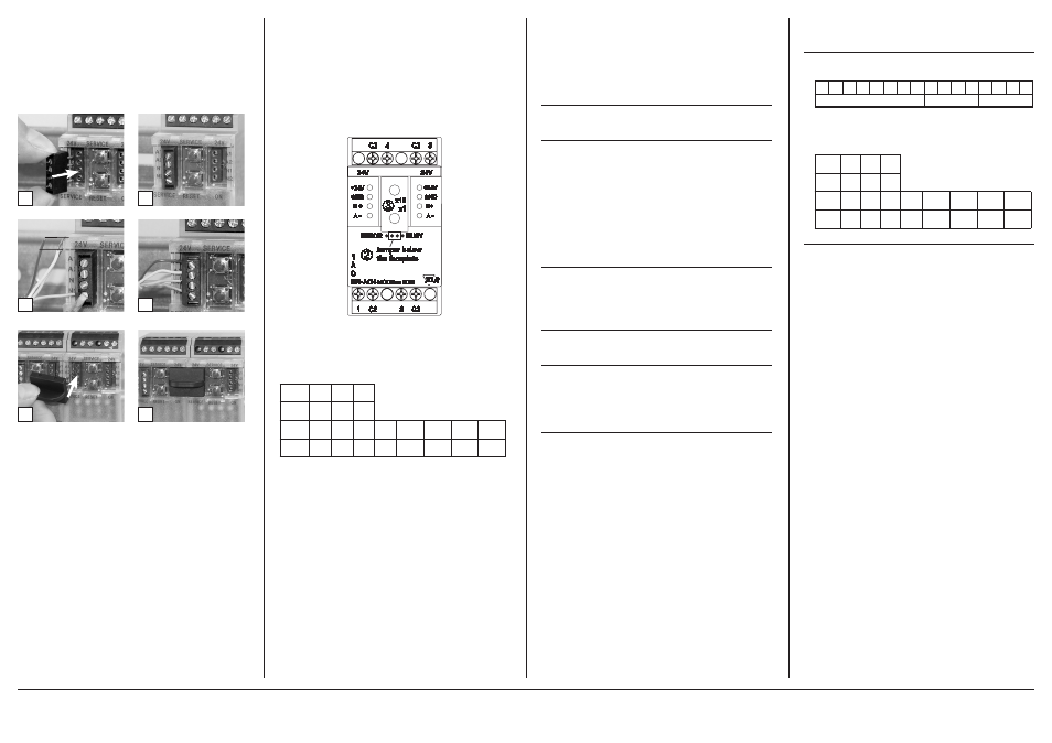
7. Bit rate and Parity setting
The bit rate and parity can be set in the programming mode when
ajumper is plugged behind the front cover of the module. This
jumper is removed in normal mode. A connection to the bus is
not required during bit rate setting.
The bit rate of the modules can be set in the following way:
1. remove the front cover of the module;
2. plug a jumper to the two middle pins of the 4 pole header
between the red and green LED (Á);
3. set the desired parity and bit rate with the address switches
(Â) in accordance to the chart below.
4. switch on the supply voltage of the module; it is now per-
manently saving the bit rate in an EEPROM;
5. switch off the supply voltage of the module;
6. remove the jumper from the header and place the front
cover.
If the settings differ from the settings specified in the chart the
factory setting applies.
Factory setting: 19200 Bd Even
C2
2
3
C2
4
C2
24V
24V
ERROR
1
A
O
B +
A
-
MR-AO4
B+
A
-
+24V
GND
+24V
GND
BUSY
MODBus RTU
x1
x10
Jumper below
the faceplate
Á
Â
C2
1
2
1
6. Mounting
Power down the equipment
Mount the module on standard rail (TH35 per IEC 60715 in
junction boxes and/or on distribution panels).
Installation
Electric installation and device termination shall be done by
qualified persons only, by respecting all applicable
specifications and regulations.
Plug in the terminal block for bus connection
4
3
5 mm
6
5
The module can be aligned without interspace. Use the jumper
plug to connect bus and supply voltage when the modules are
mounted in series.
The maximum quantity of modules connected in line is limi-
ted to 15 or to a maximum power consumption of 2 Amps
(AC or DC) per connection to the power supply. For any
similar block of additional modules a separate connection
to the power supply is mandatory.
Connect the cable for bus supply
Mounting in series
Switch
x1
1
2
3
4
5
6
7
8
Bitrate
(Bit/s) 1200 2400 4800 9600 19200 38400 57600 115200
Switch
x10
1
2
3
Parity even odd none
9. Software description
9.1 I/O Commands
“03 (0x03) Read Holding Registers”
Holding Register 0-3:
Output values of the outputs
Signed Integer16,
Holding Register 4-7:
Basic settings
of the output values
Request
Valid Register Starting Address 0..7 or 66
Valid Quantity of Registers
1..8 or 1
Response
Byte Count
2 x Quantity of Registers
Values Register 0..7
0x0000 to 0xFFFF
(0x7FFF = 10,24 Volt )
Einheit = 10,24V / 215 = 1V / 3200 = 0,3125 mV
Value Register 66
Time constant for communication monitoring.
Register Value = 0 (0x0000) there is no communication
monitoring, all other values are for communication monitoring
with a solution of 10 ms.
0x0000 to 0xFFFF => 0 to 655,35 seconds = 10,9 minutes
“06 (0x06) Write Single Register”
Request
Valid Register Address
0..7 or 66
Valid Value Register 0..7
0x0000 to 0xFFFF
(0x7FFF = 10,24 Volt )
Valid Value Register 66
0x0000 to 0xFFFF
(0 to 655,35 seconds )
Response
Echo of the request
“16 (0x10) Write Multiple Registers”
Request
Valid Register Starting Address 0..7
Valid Quantity of Registers
1..8
Valid Byte Count
2 x Quantity of Registers (QoR)
Valid Value Register 0..7
QoR x 0x0000 to 0xFFFF
(0x7FFF = 10,24 Volt )
Response
Function Code, Register Starting Address, Quantity of Registers
9.2 Bit rate setting with Modbus command
Parity and bit rate have the same value as when setting them by
address switch.
If Parity or Bit has the value 0, no setting or storage is carried
out.
The register content is stored in the EEPROM.
Continuation Software description
“06 (0x06) Write Single Register”
Request
Valid Register Address
0x41 ( 65 )
Valid Register Value 2 Bytes
Bit 15-8: Magic-Number 0x53 = 83 as protection against
accidental
writing.
The command will be further analysed only with this
number.
Response
Echo of Request
Example for a frame:
Slave address
0x12 Setting of rotary switch (18)
Function
0x06 Write Single Register
Register address Hi
0x00
Register address Lo
0x41 Bit rate and parity (65)
Register contents Hi 0x53 Magic-Number
Register contents Lo 0x15 Parity Even, 19200 Baud
All devices can be switched simultaneously with a Broadcast com-
mand (Slave address 0x00) However, it is advised not to do so as
this can cause problems:
- Devices from other manufacturers may have under this
address a register for a different purpose that will then be
operated in the wrong way.
- There is no feedback from the individual devices.
Consequently the control cannot immediately recognize if
the command was correctly received.
It is safer to address and switch each device individually.
The device will then answer with the old settings of parity and
bit rate. Switching will take place only afterwards. However, the
answer can get lost if the bus is disturbed.
When all devices are switched; it is advised to check communica-
tion. Any function of the device providing a feedback is suitable.
If a single function is to be used being independent from the
process periphery then the function „Diagnostic“ sub-function
„Return Query Data“ is suitable, it returns the transferred data.
If bit rate and parity setting of a device are unknown it is possible
to address the device successively with all combinations of bit
rate and parity until the device answers. Try the most likely com-
binations first. Try the lower bit rates last as they take longer.
15 14 13 12 11 10 9
8
7
6
5
4
3
2
1
0
0x53
Parity
Bit rate
Bit 3-0
1
2
3
4
5
6
7
8
Bit rate 1200 2400 4800 9600 19200 38400 57600 115200
Bit 7-4
1
2
3
Parity even odd none
METZ CONNECT | Im Tal 2 | 78176 Blumberg | Germany | Phone +49 7702 533-0 | Fax +49 7702 533-433
Distributed by RIA CONNECT GmbH and BTR NETCOM GmbH
Mounting instruction see www.metz-connect.com