5themethodofproducingethernetline, 6controlsystemcompinfunctiondescription, 7audiooutputs3.5mmaudiointerfaceconnectio – CREATOR WiFi Conference System User Manual
Page 13: 6 control system com pin function description
CREATOR CHINA 2013-09 WWW.CREATOR1997.COM
7
WiFi Conference System User‘s Manual
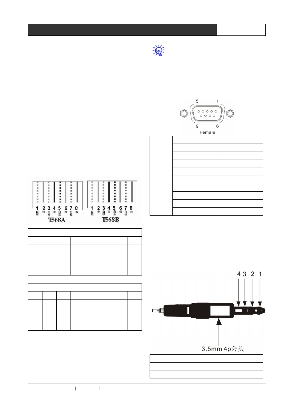
2.5 The Method of Producing
ETHERNET Line
The system adopts the CAT-5 (super 5 cable) as
the wire. Install RJ45 connector (commonly
known as crystal head) at both ends of the CAT-5
to connect network devices. The standard
connection
of
twisted
pair
cable
is
not
predetermined. The purpose is to ensure the
symmetry of the layout of cable splice, so you can
make the interference between the joint inner
cables cancel each other. General UTP line has
four pairs of twisted thin line, and marked with
different colors.
Twisted pair line has two configurations: EIA / TIA
568B standard and EIA / TIA 568A standard.
T568A linear order
1
2
3
4
5
6
7
8
whi
te
gre
en
gre
en
Wh
ite
ora
nge
blu
e
Wh
ite
blu
e
ora
nge
Wh
ite
bro
wn
bro
wn
T568B linear order
1
2
3
4
5
6
7
8
Wh
ite
ora
nge
ora
nge
Wh
ite
gre
en
blu
e
Wh
ite
blu
e
gre
en
Wh
ite
bro
wn
bro
wn
Direct line: two ends connected according to
T568B wire order standard.
Cross-line: One end connected according to
T568A line order, the other connected according
toT568B linear order standard.
Use cross-line to connect router and PC
2.6 CONTROL SYSTEM COM Pin
Function Description
Control
System
Pin
Signal
Description
1
—
—
2
RXD
Receive data
3
TXD
Send data
4
—
—
5
GND
Signal ground
6
—
—
7
—
—
8
—
—
9
—
—
2.7 AUDIO OUTPUTS 3.5mm
Audio Interface Connection
Description
Pin
Signal
Description
1
AU+
Audio signal+
2
AU-
Audio signal -