Installation sheet, Din rail mount, Dra3r dra3p – Crydom DRA Series Contactors User Manual
Page 2: Warning, Danger
Installation Sheet
DIN Rail Mount
Do not forget to visit us at:
www.crydom.com
Copyright © 2014 Custom Sensors & Technologies. Specifications subject to change without notice.
WARNING
RISK OF MATERIAL DAMAGE AND HOT ENCLOSURE
• The product's side panels may be hot, allow the product to
cool before touching.
• Follow proper mounting instructions including torque values.
• Do not allow liquids or foreign objects to enter this product.
Failure to follow these instructions can result in serious injury,
or equipment damage.
HAZARD OF ELECTRIC SHOCK,
EXPLOSION OR ARC FLASH
• Turn off power supply before
working on this equipment.
Failure to follow these instructions
will result in death or serious injury.
DANGER
Rev: 112213
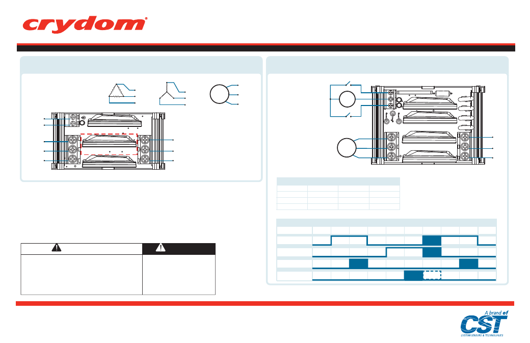
L1
L2
L3
~/- A
~/+ A
T1
T2
T3
Wiring Diagram
T1
T2
T3
T1
T2
T3
T1
T2
T3
MOTOR
DRA3R
DRA3P
L1
L2
L3
MOTOR
Source
T1
T2
T3
~/+ -/~
S1
S2
F
R
-
Wiring Diagram
S1
Open
Closed
Open
Closed
S2
Open
Open
Closed
Closed
Forward
Off
On
Off
Off
Reverse
Off
Off
On
Off
Input/Output
1
2
3
4
5
6
7
8
9
10
S1 switch
S2 switch
FWD Direction
c
e
s
m
0
0
1
c
e
s
m
0
0
1
REV Direction
100 msec
interlock
TIME DIAGRAM
(E)
(E, F)
(E, F)
(F)
(G)
(H)
(G)
(J)
(J)
(H)
(J)
(K)
No grounding wire required.
Minimum wire strip length 0.197 in (5 mm), maximum 0.235 in (6 mm) for input terminals. Minimum wire strip
length 0.315 in (8 mm), maximum 0.354 in (9 mm) for output terminals.
2 Input control terminal screws M2.5 Combo Drive.
3 Input control terminal screws M2.5 Slotted Drive.
6 Output terminal screws (L1, L2 & L3 / T1, T2 & T3) M3.5 Combo Drive.
3 Controlled legs versions only
fig. 3
Wiring Diagram for
AC 3 Phase Contactor.
fig. 4
Wiring Diagram
f or AC Motor Reversing
C ontactor.
(K)