4 - assembly – Cybex 16100 Plate Loaded Overhead Press User Manual
Page 13
Page 7
Cybex Plate Loaded 16100 Overhead Press Owner’s Manual
4 - Assembly
Tools Required
•
Rubber mallet
•
Flat head screwdriver
NOTE: It is the responsibility of the facility owner/owner of the equipment to ensure that there is appropriate
clearance around each machine to allow for safe use and passage.
NOTE: Refer to chapter 6 for reference diagrams.
1.
Read and understand all instructions thoroughly before starting any of the procedures
listed on this instruction sheet.
2.
Verify you have received the appropriate confi guration.
Verify that you received the correct color machine that you ordered.
A.
Verify you received the appropriate owner’s manual.
B.
Verify you received the warranty sheet.
C.
3. Move to desired location.
Note the diminsions of the machine:
A.
Machine Weight: 180 lbs. Size: 54” W x 53” L x 49” H
Machine Weight 82 kg. Size: 137 cm W x 135 cm L x 124 cm H
Carefully remove shrink wrap securing rubber feet and plate.
B.
4. Remove foot glides.
NOTE: Plastic shipping foot glides are used on Cybex Strength Systems machines to protect the bottom of machines
during transportation. These foot glides must be removed before a machine is first placed in service as the
shipping foot glides may cause the machine to be unstable.
WARNING: Failure to remove shipping foot glides before placing a machine in service may cause the
machine to be unstable, therefore, creating potential for personal injury or product damage.
NOTE: Failure to remove shipping foot glides before placing a machine in service may void warranty on the frames.
NOTE: Be careful not to damage frame (such as chipping the paint) when removing foot glides.
NOTE: The foot of the machine will need to be raised slightly off the floor in order to remove foot glide. Do not install
weight stack (if applicable) until after removing foot glides.
Using a rubber mallet, carefully strike foot glide.
A.
.
Using a flat blade screwdriver, carefully pry off foot glide.
B.
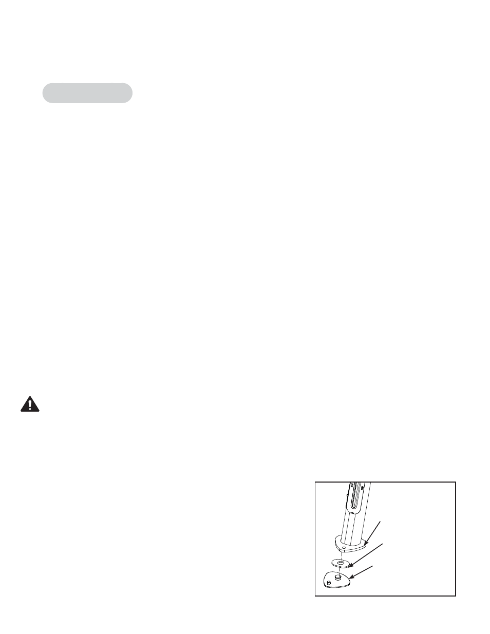
Secure plate (supplied with machine) to rubber foot
C.
before installing rubber foot to foot frame (located under seat).
See Figure 1.
Install rubber foot/plate to frame as shown in figure 1.
D.
Carefully place remaining feet on each foot of frame.
E.
Figure 1
Frame
(Located beneath
Seat)
Plate
Rubber
Foot