2 replacing the digit/driver printed circuit board, 3 schematics, 4 replacement parts list – Daktronics PC-2002 Pace Clock System User Manual
Page 20: Replacing the digit/driver printed circuit board, Schematics, Replacement parts list
14
Display Maintenance
5.2 Replacing the Digit/Driver Printed Circuit Board
1. To access the digit/driver PCB, remove the 10 outer screws to separate the front and
back panels of the display.
2. Disconnect all power and signal connections from the PCB by squeezing together the
locking tabs and pulling the connector free.
3. Remove the 8 nuts securing the PCB to the front panel of the display. Take note of the
orientation of the PCB for future reference.
4. Carefully remove the PCB from the studs and spacers on the front panel. Use an even
force to prevent any damage that might result from bending the LEDs or connector
pins on the board.
5. Position the new PCB over the studs, making sure there is a spacer between the front
panel and circuit board.
6. Tighten the 8 nuts.
7. Reconnect all power/signal connectors.
Note: These are keyed connectors and will attach in one way only. Do not attempt to
force the connections.
8. Close and secure the back panel, then power on and test the display.
5.3 Schematics
For advanced scoreboard troubleshooting and repair, it may be necessary to consult the
schematic drawing. Drawing A-187843 in Appendix A shows detailed power and signal
wiring diagrams of internal display components.
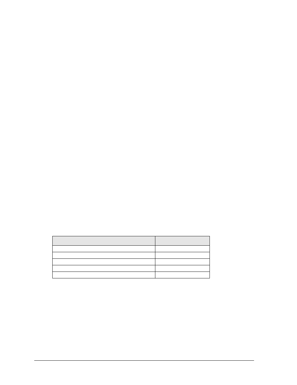
5.4 Replacement Parts List
Refer to the following table for Daktronics replacement parts:
Description
Daktronics Part #
Indoor PCB
0P-1153-0005
Flush Mount Hardware
0A-1153-0411
Surface Mount Hardware
0A-1153-0412
12 V Buzzer
DS-1487
Transformer, 120 V AC
T-1082