Section 5, Electrical installation, Power connection – Daktronics Rear-Ventilated GalaxyPro GP3 Series User Manual
Page 14: 1 power connection
9
Electrical Installation
Section 5: Electrical Installation
This section explains the steps necessary to make final electrical connections to the display from the
primary power source. For display-specific power requirements, refer to the shop drawing or label on the
display’s back.
Electrical Installation Dos
• Follow all installation guidelines
• Route power to the display through a disconnect switch
• Provide the required power per display requirements
• Provide a separate circuit for each display
• Connect each display face to a dedicated earth-ground electrode
• Follow all local and national electrical codes
Electrical Installation Don’ts
• Share circuits between displays and other electrical devices
• Connect the display to any voltage other than that listed on the product label
• Connect the neutral to the ground at the disconnect or the display
• Use the display support structure as an earth-ground electrode
5.1 Power Connection
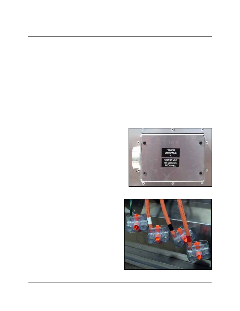
1. Review the power requirements for the
display. Requirements are found on the
display shop drawing or label on the
display’s back, as shown in Figure 9.
2. Route conduit from the main distribution
panel/disconnect to each display power
entrance. Each display section has a power
entrance and requires a dedicated circuit.
3. Remove the four screws that attach the
power entrance access door.
4. Connect conduit to the 2” Myers hub at
the left of the power entrance box.
5. Feed power cable from the conduit into
the power entrance box.
6. Connect the power ground wire to the
appropriate tap (green wire), as shown in
Note: Use a
3
/
16
” hex head wrench to
tighten screws that hold wires in place.
Figure 9: Display Power Requirements Label
Figure 10: Power Entrance Box