Daktronics DataTime Outdoor LED Time & Temperature Displays User Manual
Page 19
Wiring from Indoor J-Box to Host Driver Enclosure
J-Box
Pin Number
Cable
Color
Enclosure Terminal Block
Pin 5
White
Signal IN (-)
Pin 6
Green
Signal IN (+)
Pin 8
Brown
Signal OUT (+)
Pin 9
Blue
Signal OUT (-)
5. Mount the temperature sensor as described in Section 2.4, and connect the quick
connect cable to the four-pin quick connect on the back of the display.
6. The DataMaster controller plugs into the J-box using a DB9M to DB9F serial cable.
7. Plug the wall pack transformer into a wall socket and the other end into the DM-100
controller.
8. Client Definitions and Address Settings
Reference Drawings:
Multipurpose 4 Column LED Driver II Specifications ............................. Drawing A-166216
Host/Client Definitions ............................................................................ Drawing A-185236
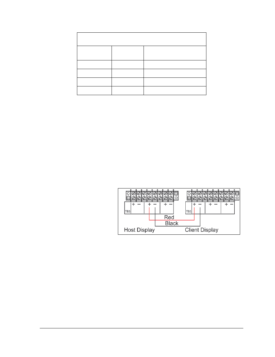
One driver at each display
installation is designated as
the “host driver,” and all
other displays are “clients.”
The “Signal OUT” terminals
on the host are used to
connect to the “client
drivers.” Refer to Figure 11
and Drawing A-185236 for
an illustration of the
client/host display
connection.
Client drivers receive signal from the host driver on the “Signal IN” terminals and can re-
drive this signal to other “client drivers” on the “Signal OUT” terminals.
The maximum wire distance between the host driver and client driver is 2000 feet.
Figure 11: Host, Signal Out to Client, Signal In
Electrical Installation
15