Power installation, Power connection, Power installation -5 – Daktronics AF-3300-12-RGB/20-R User Manual
Page 23: Power connection -5, Figure 16: connections in power termination j-box
The material of an earth-ground electrode differs from region to region and from
conditions present at the site. Consult the National Electrical Code and any local
electrical codes that may apply. The support structure of the display cannot be used
as an earth-ground electrode. The support is generally embedded in concrete, and if
in earth, the steel is either primed or it corrodes, making it a poor ground.
A minimum of one grounding electrode must be installed for each display face. The
grounding electrode is typically one grounding rod for each display face. Other
grounding electrodes as described in Article 250 of the National Electric Code may
be used. Daktronics requires that the resistance to ground be 10 ohms or less. If the
resistance to ground is higher than 10 ohms, it will be necessary to install additional
grounding electrodes to reduce the resistance. The grounding electrode should be
installed within 25 feet of the base of the display. The grounding electrode must be
connected to the ground terminal lug on the back of the display.
Power Installation
There are two considerations for power installation: installation with ground and
neutral conductors provided, and installation with only a neutral conductor provided.
For these displays, installation with ground and neutral conductors provided is used.
Installation with Ground and Neutral Conductors Provided
For this type of installation, the power cable must contain an isolated earth-ground
conductor. Under this circumstance, do not connect neutral to ground at the
disconnect or at the display. This would violate electrical codes and void the
warranty. Use a disconnect so that all hot lines and neutral can be disconnected. The
National Electrical Code requires the use of a lockable disconnect within sight of or
at the display.
Power Connection
Reference Drawings:
Schematic, Power Term Panel, 1 Circuit ..................... Drawing A-211950
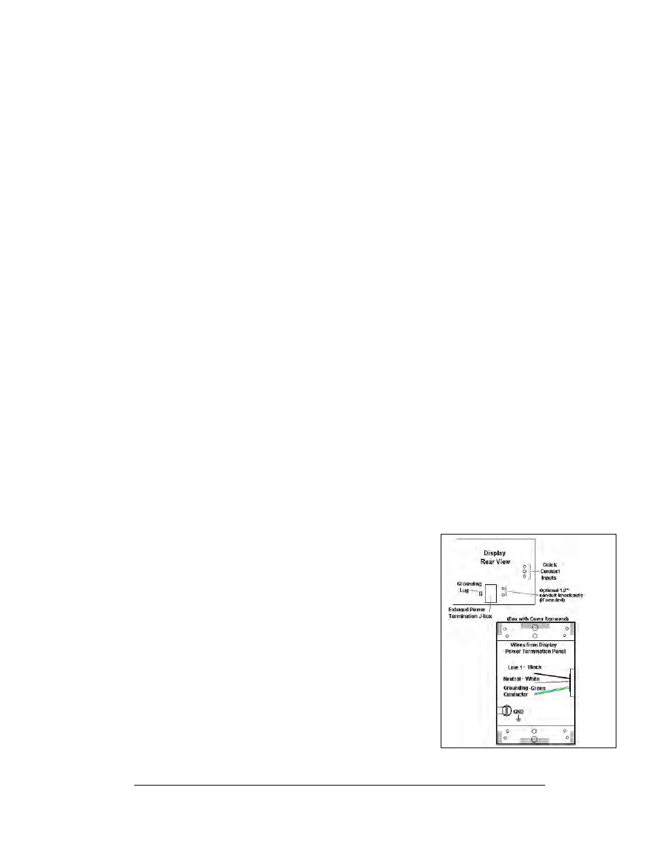
Figure 16: Connections in Power
Termination J-box
Display power is connected to the power termination
enclosure on the back of the display. Complete the
following steps to terminate the hot, neutral, and ground
wires at the termination enclosure.
1. Route the power cable through ½” conduit to the
rear of the display and into the power termination
enclosure.
2. The power termination enclosure will contain two
wires plus a ground coming from the interior of
the display – these wires are pre-terminated to the
power termination panel inside the display
3. Inside the external power termination J-box,
connect the power wires to the wires coming from
the display interior using wire nuts. Refer to
for further information.
Electrical Installation
3-5