Daktronics G-1000-34-R User Manual
Page 33
Maintenance &
Troubleshooting
4-6
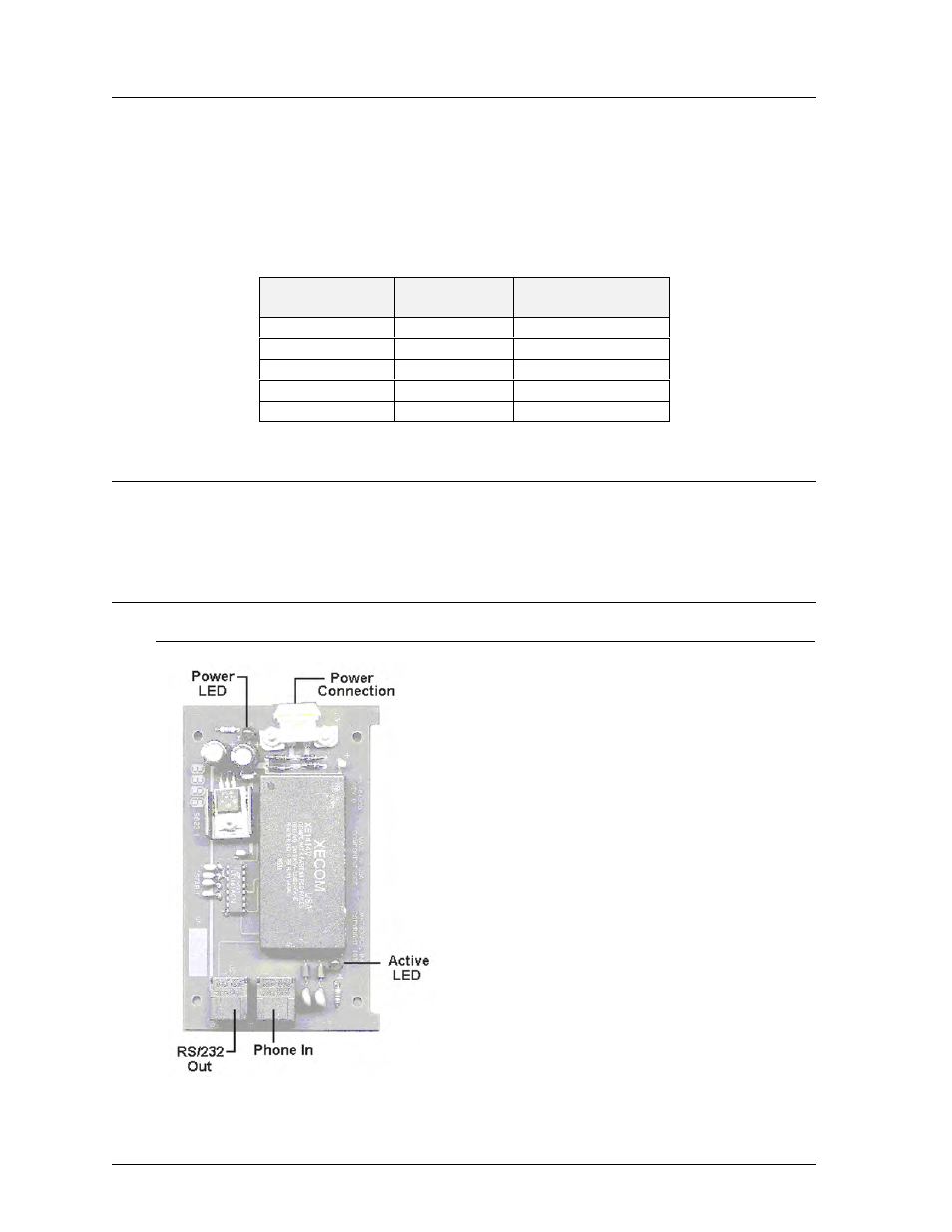
Figure 13: Modem
4.7
Light Detector
Reference Drawings:
Schematic . . . . . . . . . . . . . . . . . . . . . . . . . . . . . . Drawing C-87896
Overall Dimensions; G-1000 . . . . . . . . . . . . . . . Drawing A-88154
The light detector is internally mounted and wired at Daktronics. It is located behind the lower left
(front view) module bracket (Drawing A-88154, Section 1). A 4-conductor cable is used to
connect the light detector to the display. The cable is terminated at the terminal block on the light
sensor and at the terminal block on the controller board (Refer to Drawing C-87896).
Light Detector
Cable Wires
Controller Board
Pin No.
Color
Pin No.
1
Green
3
2
White
4
3
Red
1
4
Black
2
N.C.
Bare
2
4.8
Transformer
The transformer is used to provide power to the controller board (refer to Section 4.6). It is
located in the bottom left corner (front view) of the display.
4.9
Modem
4.9.1
Accessing and Replacing the Modem
If a modem was included with your display, it is located
inside the display next to the controller board.
1. To replace a modem, first disconnect the power
and signal connections (refer to Figure 13 for
disconnection of power).
2. The modem is held in place with the use of plastic
rails known as “snap track.” Carefully “snap” the
modem out of the rails.
3. Insert the new modem by first laying one end into
the rails of the “snap track,” then pivot it around
and snap into place.