Daktronics AB-1600-1.5,2.5 User Manual
Page 28
Electrical Installation
3-8
disconnect(s) and wire for power distribution to the multiple breaker boxes. This customer supplied
fused main disconnect is considered the service entrance point.
Due to the inrush current required by the transformers on start-up, the main disconnect may have to
be oversized or use hi-magnetic trip breakers to handle this momentary inrush current requirement.
An alternative is to shut down the individual breakers on the panelboard before turning on the main
disconnect and then turn on the panelboard breakers individually.
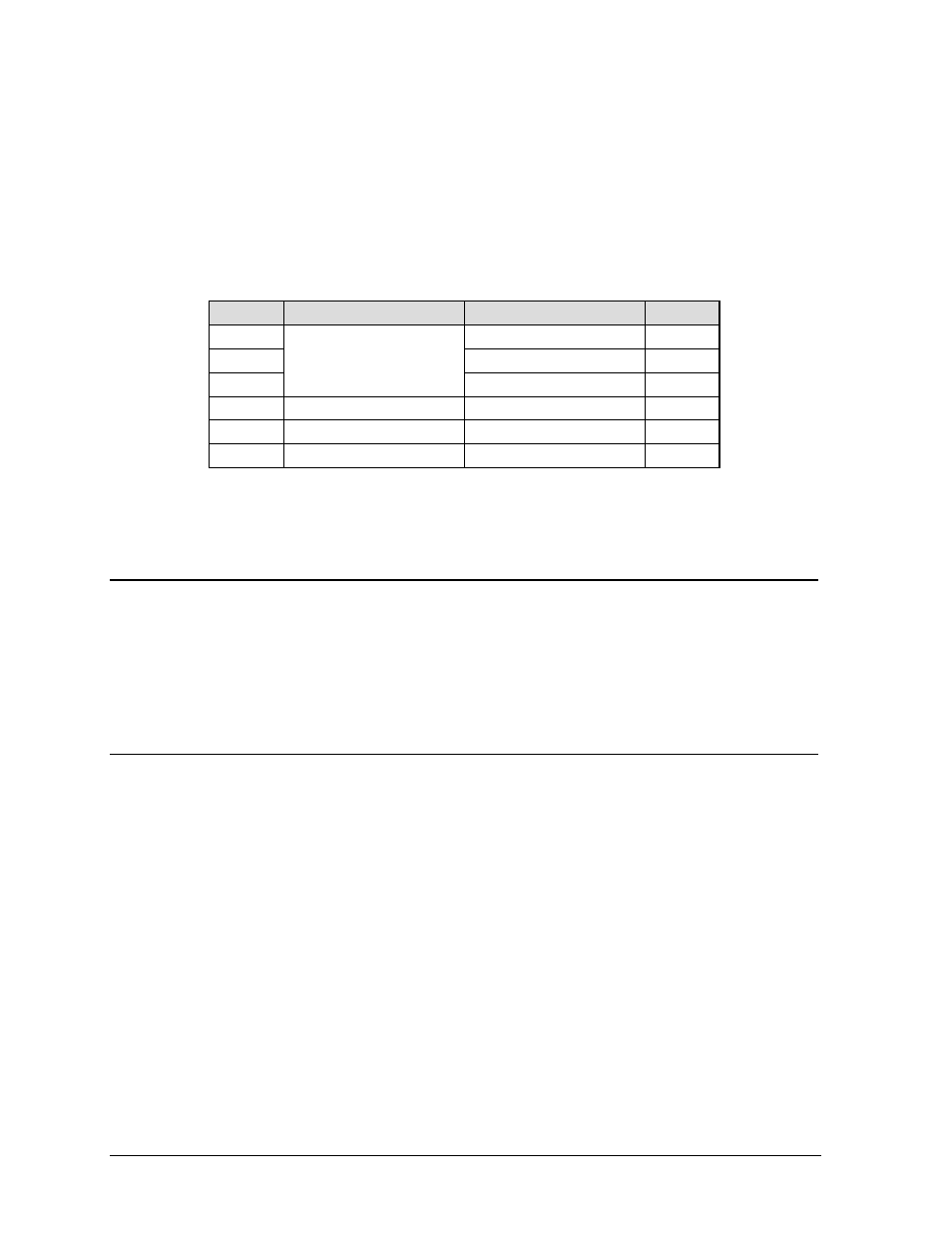
The following table illustrates a typical panelboard wiring list. A list similar to this is located inside
the panelboard door. The Square D 30 amp QA breaker is UL listed for 1 or 2 #10 AWG wire(s).
Breaker
Wire
Wire
Breaker
1
W101P & W201P (T1)
2
3
Main
W102P & W202P (T2)
4
5
W103P & W203P (T3)
6
7
W104P & W204P (T4)
Not Used
8
9 Spare
Not
Used
10
11
Not Used
Not Used
12
=
Included with the panelboard is a surge suppresser not wired at the factory. Refer to Drawing A-
74902 for the wiring of the surge suppresser.
3.7
Configuring the Display Transformers
Reference Drawing:
Transformer Configuration (Voltage Taps) ............................................ Drawing A-77128
The transformer used in this display has a 12V output to the lamp. Refer to Drawing A-77128 in
Appendix B for information on configuring the transformer for variable incoming voltage.
3.8
Line Receiver Electrical Installation
Reference Drawings:
Shop Drawing, 32YYY-10 S1600......................................................... Drawing B-103031
Shop Drawing, 40YYY-10 S1600......................................................... Drawing B-103032
Shop Drawing, 48YYY-10 S1600......................................................... Drawing B-102149
Shop Drawing, 56YYY-10 S1600......................................................... Drawing B-103034
Shop Drawing, 64YYY-10 S1600......................................................... Drawing B-103035
Shop Drawing 72YYY-10 S1600.......................................................... Drawing B-103036
If the display has a line receiver, Figure 29 illustrates the data signal connection to the display. If the
display has a data distributor, skip to the sub-section titled Data Distributor Electrical Installation. For
a description of the difference between a display with a line receiver and a data distributor refer to
Section 1.3.
Note: Refer to Drawings B-103031, B-103032, B-102149, B-103034, B-103035 and B-103036 in
Appendix B for the location of the line receiver in the display. To access the inside of the display,
refer to Section 4.6.