Daktronics Hoist Operation and Maintenance Manual User Manual
Page 8
5
Hoist operation
Hoist operation:
The Remote Control Station is the main point of operation for this S Series hoist system, and where
system control is turned ON/OFF. RAISE/LOWER control is also possible through the handheld and
wireless pendants. If the handheld pendant is not in use, either it or the provided jumper plug must be
plugged into the Remote Control Station to ensure operation, otherwise control will be impossible.
To raise a hoist, simply press and hold the RAISE
button (Figure 2)
on which ever method of control
you are utilizing. The hoist will travel upward until it
hits the upper limit or you release pressure from the
momentary push button.
To raise a hoist, simply press and hold the RAISE
button on which ever method of control you are
utilizing. The hoist will travel upward until it hits
the upper limit or you release pressure from the
momentary push button.
Lowering the hoist works the same way, by pressing
the LOWER button. It’ll continue to lower until it reaches the lower limit of travel or you release the
button.
If you need to stop the hoist immediately press the EMERGENCY STOP button, and all hoist movement
will cease. The hoist won’t be operational again by any controller until the EMERGENCY STOP button
that was pressed is depressed, and the indicator light turned off.
The FAULT RESET button and indicator light correspond to when an overtravel
or VFD fault is being experienced. If you observe such a fault to cause this light
to go on, call Daktronics immediately for further instructions so that we can
understand the nature of the fault and guide you through a reset procedure.
To lower a hoist, turn the UP/OFF/DOWN selector switch for the desired hoist
to the down position and press RUN. The hoist will run at full speed and will run
until the button is released or the hoist reaches its lower hard-struck limit switch.
Up to 4 hoists can be run at one time using multiple selector switches. The hoists will run in the direction
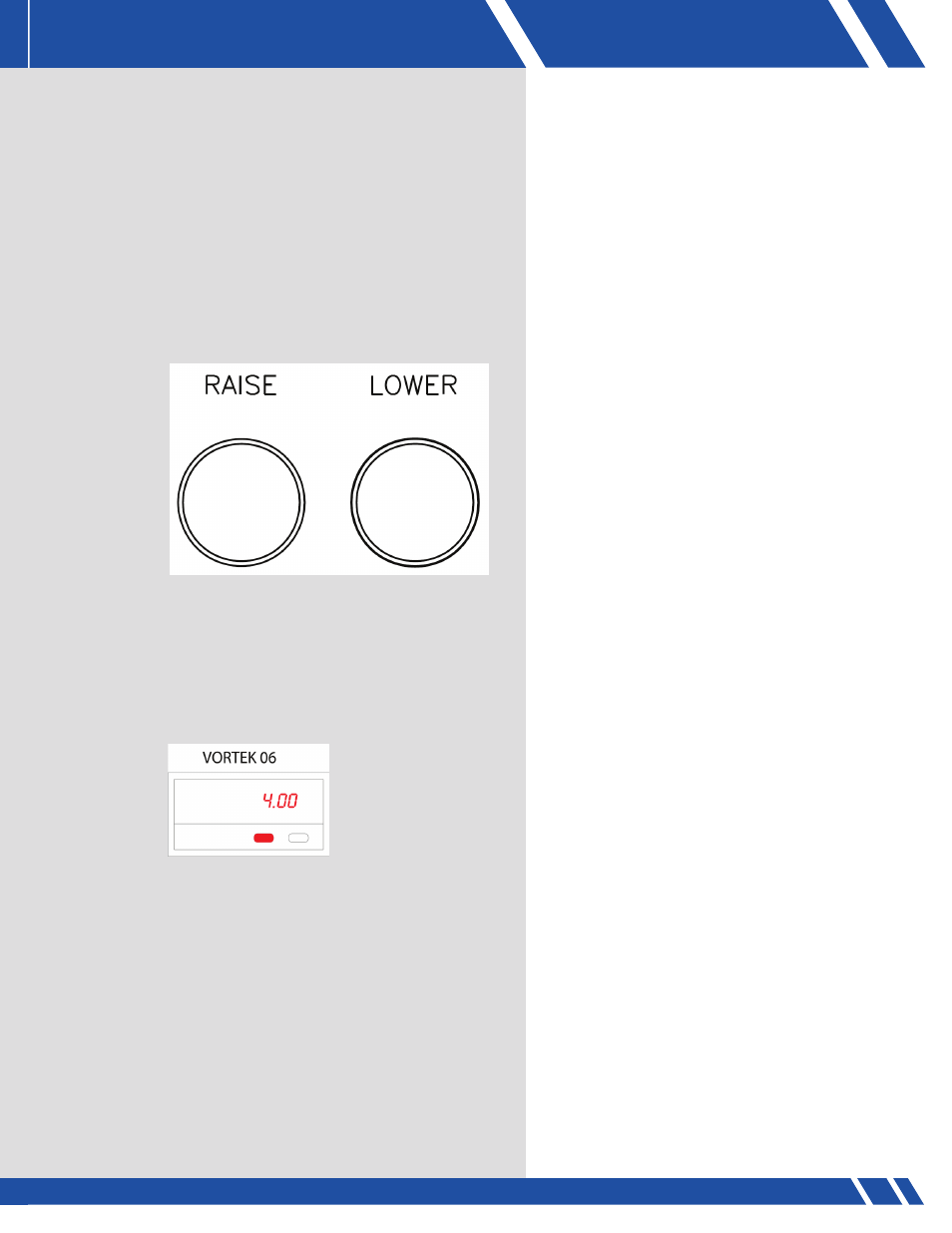
selected, meaning that some could be running up and others down. The position displays show the
height above the floor for each batten (Figure 3). This is set during initial installation and should not
need to be changed.
However, with these displays, whenever the red button is pushed, it re-sets the display to a pre-set
number which is 4.00 ft even if the batten is above or
below 4.00 ft.
To set the display so that the batten height above floor is correct, lower (or raise) the batten to 4 ft (have
someone measure with a tape measure to the BOTTOM of the batten) and then push the red button on
the display.
FIgURE 2: Selector switches
FIgURE 3: Position display