Chapter 5 – DFI DT122-SB Manual User Manual
Page 28
www.dfi .com
28
Chapter 5 Ports and Connectors
Chapter 5
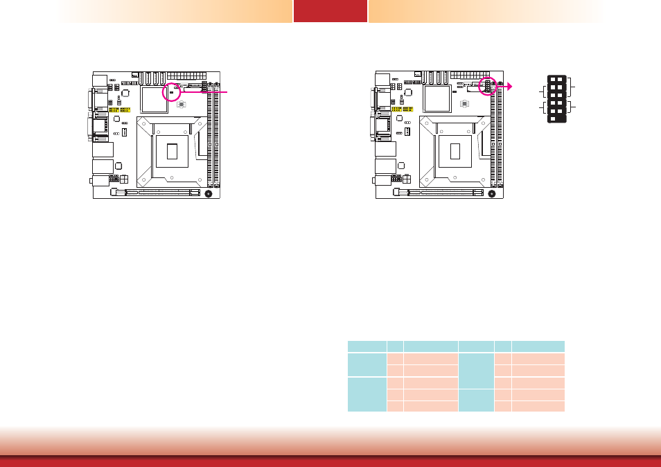
Standby Power LED
This LED will lit red when the system is in the standby mode. It indicates that there is power
on the system board. Power-off the PC and then unplug the power cord prior to installing any
devices. Failure to do so will cause severe damage to the motherboard and components.
Front Panel Connectors
HDD-LED - HDD LED
This LED will light when the hard drive is being accessed.
RESET SW - Reset Switch
This switch allows you to reboot without having to power off the system.
PWR-BTN - Power Switch
This switch is used to power on or off the system.
PWR-LED - Power/Standby LED
When the system’s power is on, this LED will light. When the system is in the S1 (POS - Power
On Suspend) state, it will blink every second. When the system is in the S3 (STR - Suspend To
RAM) state, it will blink every 4 seconds.
Pin Pin Assignment
Pin Pin Assignment
HDD-LED
3
HDD Power
PWR-LED
2
LED Power
5
Signal
4
LED Power
RESET SW
7
Ground
6
Signal
9
RST Signal
PWR-BTN
8
Ground
11 N.C.
10
Signal
1
Standby
Power LED
1
HDD-LED
RESET-SW
PWR-LED
PWR-BTN
12
11
2
1