Board layout and jumper settings, Top view bottom view – DFI KS200 Installation Guide User Manual
Page 3
3
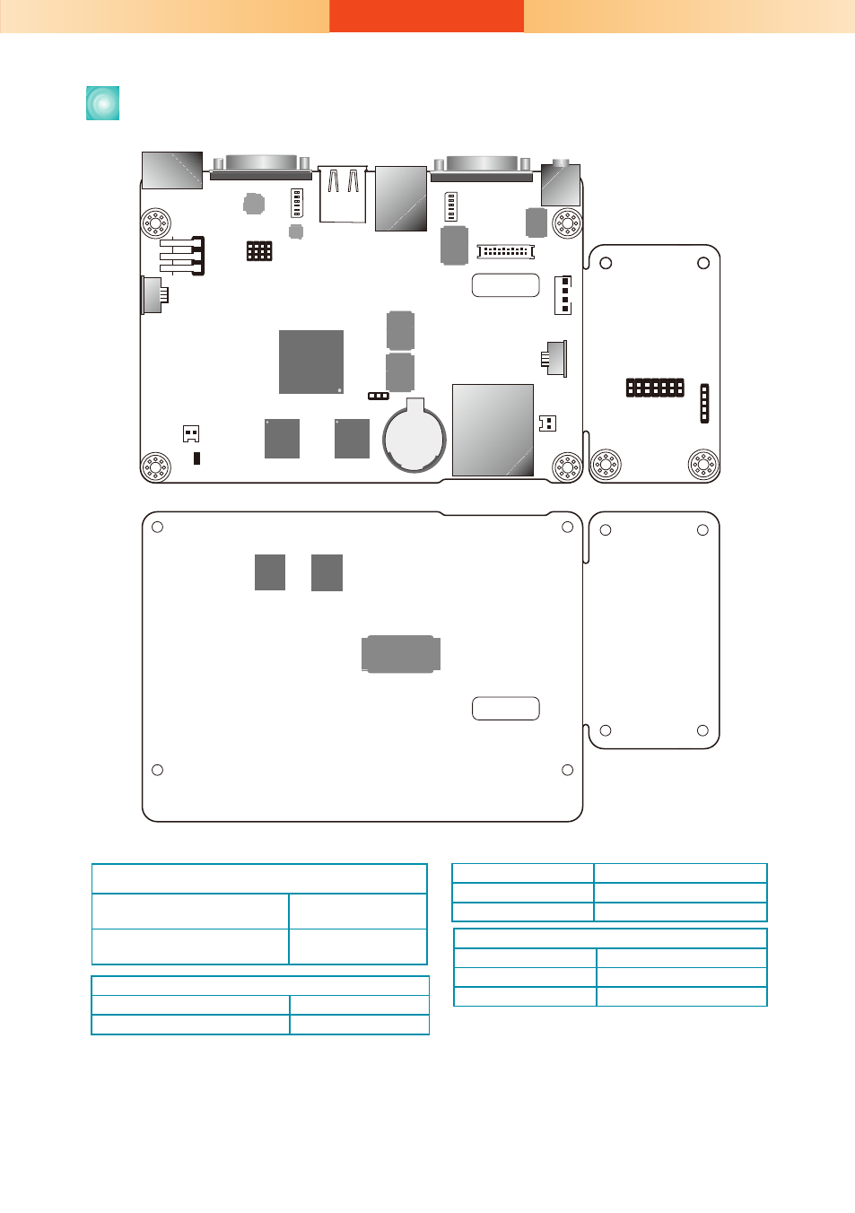
Board Layout and Jumper Settings
COM 1
COM 2
Line-out
3
1
10
12
COM2 RS232/422/485 HW/SW Select(JP7)
SD/MMC
Reset
1
Amplifier 2W
Connector
1
2
19
20
LVDS LCD Panel
LED Connector (external)
USB 1-2
1
ON
2
3
4
5
6
Standby Power LED
LAN 1
1
ON
2
3
4
5
6
SW3
Touch
Connector
(default)
LVDS83B
1
14
DIO
1
5
Touch
Connector (option)
DC-in
SW4
Power SW
Battery
1
Clear CMOS(JP1)
1
1
1
AM3517AZCN
DDR2
DDR2
128M
Android Hot Key Connector
128M
USB 2514BI
AIC23B
SP338EER1
AVC
16T245
AVC
16T245
NAND Flash
DDR2
DDR2
128M
128M
TOP VIEW
BOTTOM VIEW
Clear CMOS Data
JP1
Normal (default)
1-2 On
Clear CMOS Data
2-3 On
Boot Sequence (SW3)
MMC Boot
1-4 On, 2-3 Off
NAND Boot
1-4 Off
RS232/RS422/RS485 HW/SW Select: COM 2 (JP7)
Set via Software
1-4-7-10
2-5-8-11 On
Set via Hardware
2-5-8-11
3-6-9-12 On
RS232/RS422/RS485 Select: COM 2(SW4)
RS232
1 On, 2-3 Off
RS422
1-2 On, 3 Off
RS485
2 On, 1.3 Off
Note: If you use SW4 to select RS232/ RS422/ RS485, make
sure JP7 is set to “Set via Hardware”.
934-KS2000-0A0G
A23212304