Chapter 3 – DFI CR901-B User Manual
Page 31
www.dfi .com
Chapter 3 Hardware Installation
31
Chapter 3
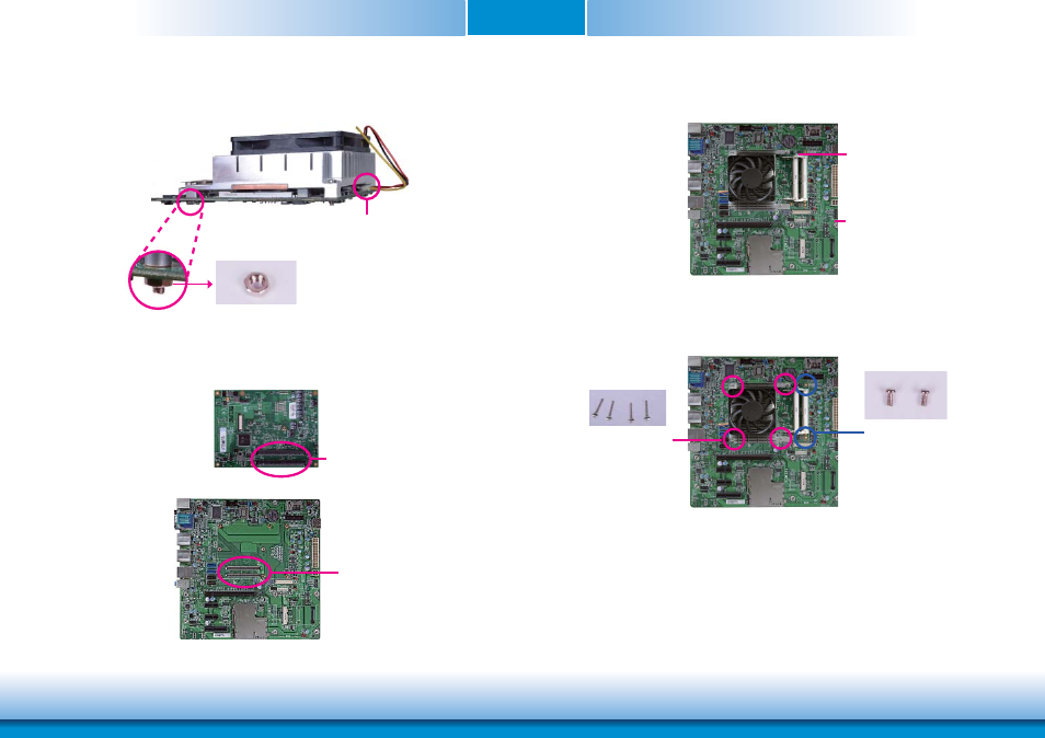
8. From the bottom of the board, fasten the provided bolt into the screw and then connect
the cooling fan’s cable to the fan connector on CR901-B.
Fan connector
Bolt
9. Grasping CR901-B by its edges, position it on top of the carrier board with its mounting
holes aligned with the bolts on the carrier board. This will also align the COM Express
connectors of the two boards to each other.
COM Express connec-
tors on CR901-B
COM Express connectors
on the carrier board
11. Use the provided mounting screws to secure CR901-B with heat sink to the carrier board.
The photo below shows the locations of the long/short mounting screws.
Carrier board
Short screws
10. Press CR901-B down firmly until it is completely seated on the COM Express connectors of
the carrier board.
CR901-B
Long screws