Chapter 2 – DFI CD951-C series User Manual
Page 13
www.dfi.com
13
Chapter 2 Hardware Installation
Chapter 2
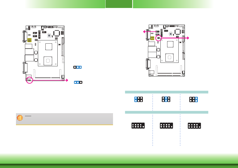
COM2 RS232/RS422/RS485 Select
5-6 On: RS485
JP3 is used to configure the COM ports to RS232, RS422 (Full Duplex) or RS485.
The pin function of the COM ports will vary according to the jumper’s setting.
JP3
6
4
2
5
3
1
COM 2
JP3
RS232
RS422
Full Duplex
RS485
COM 2
6
4
2
5
3
1
1-2 On: RS232
(default)
3-4 On: RS422
Full Duplex
6
4
2
5
3
1
2
1
9
D
ATA
+
N.C. N.C. N.C. N.C.
D
ATA
-
N.C. N.C. N.C.
9
RXD+ TXD+ N.C. N.C. N.C.
RXD- TXD- N.C. N.C.
2
1
9
DCD- TD GND RT
S-
RI-
RD
D
TR-
DSR
-
CT
S-
2
1
Power-on Select
1-2 On:
Power-on via power button
(default)
2-3 On:
Auto power-on
JP5
3
1
2
3
1
2
JP5 is used to select the method of powering on the system. If you want the system to
power-on whenever AC power comes in, set JP9 pins 2 and 3 to On. If you want to use the
power button, set pins 1 and 2 to On.
When using the JP5 “Power On” feature to power the system back on after a power failure
occurs, the system may not power on if the power lost is resumed within 5 seconds (power
flicker).
Note:
In order to ensure that power is resumed after a power failure that re covers within a
5 second period, JP9 must be set to pins 2-3 and the “AC Power Lose” in CMOS is set
to “On”.