ETA 0609 User Manual
Page 15
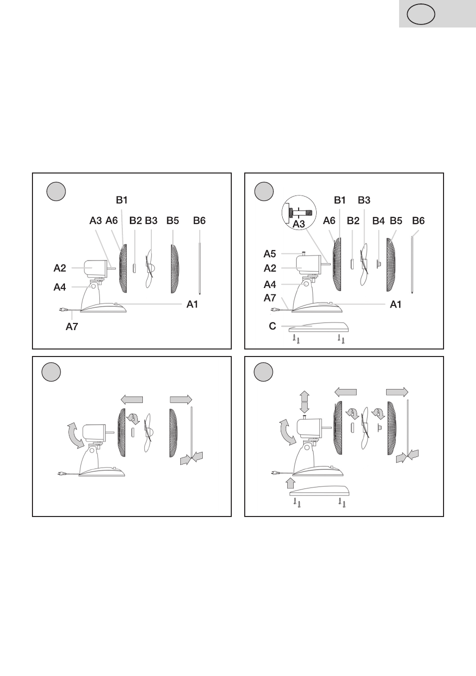
II. DESCRIPTION OF THE APPLIANCE (Fig. 1, 2)
A – fan
A1 – control panel
A5 – control of fan turning (only for type eTA 1609)
A2 – drive unit
A6 – fan holder
A3 – drive shaft
A7 – power cord
A4 – tilting hinge
B – blade wheel cover
B1 – back cover
B4 – securing matrix (only for type eTA 1609)
B2 – securing matrix
B5 – front cover
B3 – blade wheel
B6 – connecting material
C – stand (only for type eTA 1609)
ETA 0609
ETA 1609
1a
ETA 0609
2a
ETA 1609
1
2
III. PREPARATION FOR USE
Remove all the packing material and take out the fan. Remove all possible adhesion foils,
stick-on labels or paper from the appliance.
Assembling the fan blade wheel cover (Fig. 1a, 2a)
Unscrew matrix
B4 from drive unit A2 clockwise (applies to type eTA 1609) and matrix B2
anticlockwise. Set back cover
B1 to drive A2 so that the projections on the drive unit case
snap in the holes in cover
B1. Secure the case by screwing matrix B2 clockwise and fix it
tightly.
15
GB
/ 42