Flowserve MJ Slurry User Manual
Page 15
MJ SLURRY USER INSTRUCTIONS ENGLISH 71569294 - 02/08
Page 15 of 42
®
4 INSTALLATION
Equipment operated in hazardous locations
must comply with the relevant explosion protection
regulations. See section 1.6.4, Products used in
potentially explosive atmospheres.
4.1 Location
The pump should be located to allow room for
access, ventilation, maintenance and inspection with
ample headroom for lifting and should be as close as
practicable to the supply of liquid to be pumped.
Allow sufficient room to facilitate the back pull-out
feature on V-belt driven units.
Refer to the general arrangement drawing for the
pump set.
4.2 Part assemblies
Motors may be supplied loose on M Slurry pumps,
typically on frame sizes 400 and above. It is the
responsibility of the installer to ensure that the motor
is assembled to the pump and lined up as detailed in
section 4.5.2.
4.3 Foundation
The foundation may consist of any
material that will afford permanent, rigid support to
the top plate. It should be of sufficient size and mass
to absorb expected strains and shocks that may be
encountered in service. The sump opening must be
large enough to pass the pump liquid end and
discharge piping. The top surface must be flat and
level for future pump alignment.
In the cases where maximum support is desired or
where levelling problems are anticipated a sole plate
(as illustrated in Figure 1) may be used as the
bearing surface for the top plate. A sole plate is
sometimes referred to as a curb ring. When a sole
plate is used it should be bolted to the concrete
foundation and grouted into position.
Foundation bolts should be high strength steel (SAE
GR 5 or equal). Each bolt should be surrounded by a
pipe sleeve two or three times the diameter of the
bolt. The sleeve should be securely anchored and
designed to allow the bolts to be moved to align with
holes in the top plate or sole plate as required. The
bolts should be sufficiently long to allow for leveling
shims or wedges. Extra long bolts can be shortened
after the installation is complete.
4.3.1 Sole Plate Installation.
Position the sole plate next to the foundation and
clean the foundation surface thoroughly. Remove the
rag packing from the pipe sleeve and place wedges
or shims as close to the foundation bolts as possible.
Leveling nuts may be used on the bolts instead of
wedges.
Sole plates are normally not supplied by Flowserve.
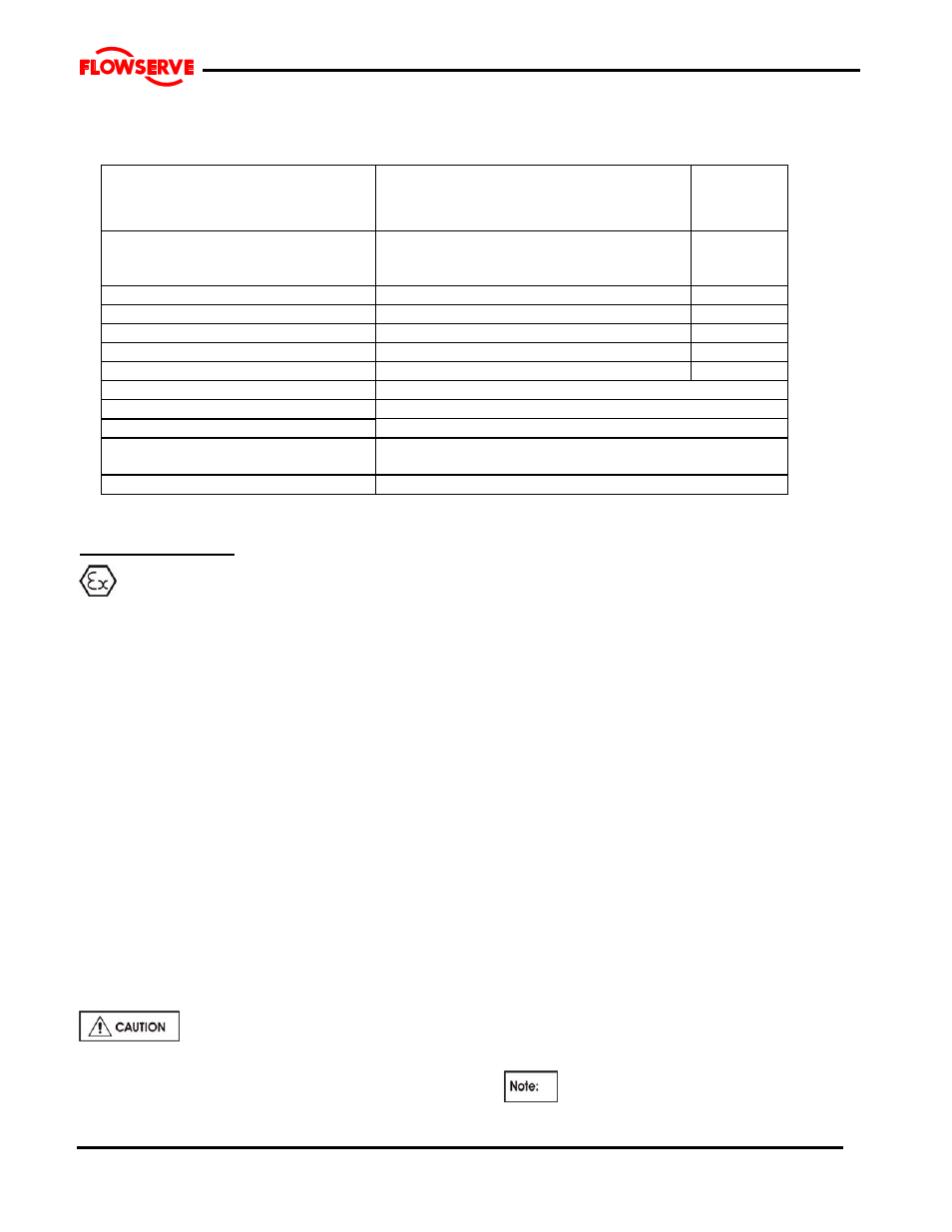
MATERIALS OF CONSTRUCTION
(LIQUID END)
BASIC
CONSTRUCTION
MATERIAL
CLASS
CASING
IMPELLER
WEAR PLATE
ASTM A532 CL III TYPE A
LOWER BEARING HOUSING
ASTM A48 CL35
IMPELLER SPACER
HARD STEEL –360 BHN
SHAFT SLEEVE
ASTM A743 CG8M
SHAFT AISI
1045
WATER LUBRICATED BEARINGS
316 SS W/ BUNA-N LINER
WEAR PLATE STUDS & NUTS
AISI 316
GASKETS-CASING SYNTHETIC
FIBRE
MISC. FASTNERS,
PARTS
STEEL