Flowserve HWX Worthington User Manual
Page 31
HWX USER INSTRUCTIONS ENGLISH - 07/14
Page 31 of 40
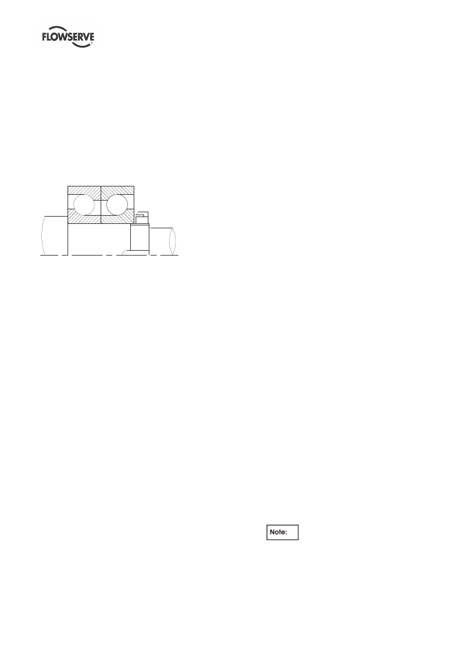
wide flange of the outer race towards the
coupling. The outer thrust bearings is to be
placed on the shaft with the wide flange of the
outer race towards the inner bearing
.
d) When installing bearings on shaft, heat thrust
bearing, radial bearing and screw pump (oil
cascade lubricated bearing housing) to 200-230°F
(95-110°C) and slide them up against their
shoulders on shaft (thrust bearing on coupling
end of shaft and radial bearing and screw pump
on impeller end). Heat for approximately 20 - 30
minutes.
e) Install the lock washer and locknut as per figure
6.6 (oil cascade and oil mist lubrication).
Figure 6.6 - Oil Cascade and Oil Mist Lubrication -
•
Slide thrust bearing lock washer onto shaft,
then thread lock nut onto shaft hand tight.
•
Spin outer races of thrust bearing several
times, then tighten the lock nut. The lock nut
should be tightened such that the outer races
of the thrust bearing do not turn
independently when spun, but can be moved
independently by hand.
•
Allow the thrust bearings to cool to ambient
temperature.
•
Loosen the thrust bearing lock nut to hand
tight, then re-torque the lock nut to 122 Nm
(90 ft-lb).
•
Mount a dial indicator on the shaft to read on
the outer thrust bearing races. Runout on the
outer thrust bearing races should not exceed
0.04 mm (0.0015 in.). Tap the bearing races
into place with a soft-faced mallet if
necessary.
•
When bearing nut has been properly
tightened and runout are within specification,
bend a lock washer tab into a slot on the lock
nut.
f) Remove shaft from vise.
g) Place the bearing housing in a vertical position on
blocks in preparation for installation of shaft
assembly. Make sure blocking is of sufficient
height so that shaft will not contact the floor.
There should be 0.03 mm (0.001 in.) diametrical
clearance between outer race of each bearing
and its bore in the bearing housing.
h) Suspend shaft vertically for installation into
bearing housing.
i)
If your pump is oil lubricated, and the inner
bearing housing cover [3260] has been removed,
then install a new O-ring, or coat the mating
surfaces of the bearing housing [3200] and cover
with Loctite Gasket Eliminator 504 sealant (or
equivalent], as indicated in the Cross Sectional
Drawing in the back of this manual. Install bearing
housing end cover and evenly tighten cap screws.
j)
Lubricate outer races of thrust bearings [3013]
and radial bearing [3010]; then slide the shaft with
bearings installed into the bearing housing [3200].
Push or tap on the outer thrust bearing race with
a soft brass or plastic rod to position bearings in
their bores in bearing housing.
k) Install the bearing isolator [4330] in the bearing
housing end cover [3260.2].
l)
Coat the mating surfaces of the bearing housing
[3200] and bearing housing end cover [1220] with
Loctite Gasket Eliminator 504 sealant (or
equivalent]. If your pump is oil lubricated, then
coat and install the cover plate [3260] as well.
Install bearing housing end cover (and cover
plate, if applicable) and evenly tighten cap
screws.
m) Determine thrust bearing axial play as follows:
•
Mount a dial indicator to read on end of shaft.
Push on coupling end of shaft until shaft is all
the way toward impeller end; then set the dial
indicator to "0".
•
Thrust shaft toward coupling end and read
indicator: Repeat the procedure to confirm
reading.
•
Clearance is correct if dial indicator is
between 0.05 mm (0.002 in.) and 0.100 mm
(0.004 in.).
•
If dial indicator indicates play less than 0.05
mm (0.002 in.) or more than 0.100 mm
(0.004 in.), correct by machining end cover or
installing appropriate gasket between bearing
housing and end cover gasket.
n) Install inboard fan [2540] and tighten cap screw.
Install vent ring [2500] and secure it with screws
[6579.4]. Mount the fan [8161] on the vent ring
[2500] with screw [6577.4]
o) Determine shaft and impeller wear ring runout as
follows:
•
With bearing housing clamped in position, fix
dial indicator to bearing housing [3200] and
touch dial indicator button to shaft [2100].
Indicator must be fixed tightly to housing.
•
Slowly, rotate shaft and record readings at
12, 3, 6, and 9 o'clock points. Total indicated
reading (TIR) shall not exceed 0.04 mm
(0.0015 in.). If readings are excessive, set up
may not be rigid.
If runout (i.e., TIR) at any surface is
excessive, check all parts for burrs, dirt and
rough surfaces; register face of bearing
housing for squareness, and its bore for
roundness; bearings for bottoming against
shaft shoulders.