7 protection systems, 5 commissioning, start-up, operation, And shutdown – Flowserve Mark 3 ISO Durco User Manual
Page 15: 1 pre-commissioning procedure, 2 setting impeller clearance, Commissioning and operation (5), Lubrication (5.1.1), Pre-commissioning (5.1), 5 commissioning, start-up, operation and shutdown
DURCO MARK 3 ISO CLOSE COUPLED ENGLISH 26999985 02-14
Page 15 of 32
flowserve.com
4.7 Protection systems
The following protection systems are
recommended particularly if the pump is installed in a
potentially explosive area or is handling a hazardous
liquid. If in any doubt consult Flowserve.
If there is any possibility of the system allowing the
pump to run against a closed valve or below
minimum continuous safe flow a protection device
should be installed to ensure the temperature of the
liquid does not rise to an unsafe level.
If there are any circumstances in which the system
can allow the pump to run dry, or start-up empty, a
power monitor should be fitted to stop the pump or
prevent it from being started. This is particularly
relevant if the pump is handling a flammable liquid.
If leakage of product from the pump or its associated
sealing system can cause a hazard it is
recommended that an appropriate leakage detection
system is installed.
To prevent excessive surface temperatures at
bearings it is recommended that temperature or
vibration monitoring are carried out.
5 COMMISSIONING, START-UP,
OPERATION AND SHUTDOWN
These operations must be carried
out by fully qualified personnel.
5.1 Pre-commissioning procedure
5.1.1 Lubrication
Electric motors are supplied pre-greased and are
normally sealed for life. If in doubt, refer to motor
instruction manual.
5.2 Setting impeller clearance
This procedure may be required after the pump has
been dismantled or a different clearance is required.
Before carrying out this procedure ensure that the
mechanical seal(s) [4200] fitted can tolerate a change
in their axial setting, otherwise it will be necessary to
dismantle the unit and reset the seal axial position
after adjusting the impeller clearance.
If a cartridge seal is fitted loosen it from the shaft.
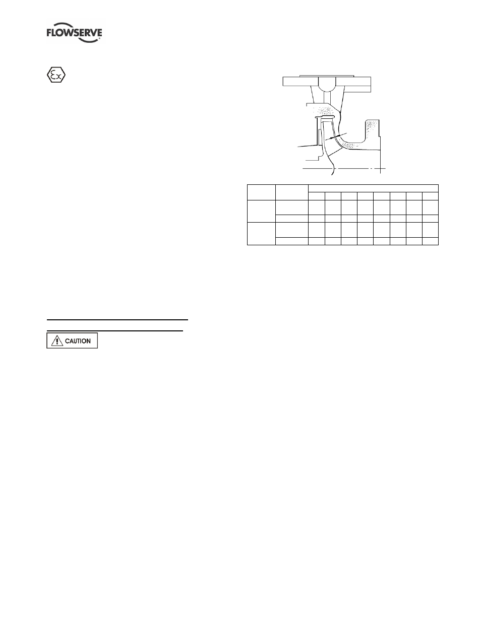
5.2.1 Setting front clearance on ISO-M open
impeller (OP)
Clearance settings:
Impeller
diameter
Motor frame size
80
90 100 112 132 160 180 200
Up to
210 mm
Clearance
(mm)
0.3 0.3 0.3 0.3 0.3 0.3 0.3 0.3
Notches
7
7
7
7
7
8
8
8
211 to
315 mm
Clearance
(mm)
0.4 0.4 0.4 0.4 0.4 0.4 0.4 0.4
Notches
8
8
8
8
8
9
9
9
a) Disconnect the muff coupling [7120] and clean up
the bores.
b) Clean motor shaft and stub shaft and deburr
where necessary.
c) Replace muff coupling [7120], ensuring that the
grub screw locates in the stub shaft.
d) The motor end coupling bolts [6570.2] should be
slacker than the pump end coupling bolts
[6570.4] so that the coupling and stub shaft can
be rotated relative to the motor shaft.
e) The motor shaft should be prevented from
rotating by using a C-spanner located in the
keyway (where possible) or by locking the fan
end of the motor [8100].
f) Rotate the coupling [7120] until the impeller
[2200] contacts the pump casing [1100]. This is
the zero clearance position or datum for setting
the front clearance.
g) Mark the bracket with a pen and, whilst preventing
the motor shaft rotating, turn the coupling [7120] in
the opposite direction by the recommended
number of notches as indicated in the table. For
the remaining steps, take care not to rotate the
pump shaft relative to the motor shaft.
h) Carefully loosen and back off the grub screw and
tighten the coupling bolts [6570.4], ensuring that the
gap is equal between the coupling halves [7120].
i)
Torque the screws to the specified values:
M8
– 30 Nm (22 lbf•ft)
M10
– 58 Nm (43 lbf•ft)
j)
Check that the shaft can turn freely without
binding.
k) If a cartridge seal is fitted it should be reset at this
point.