Direction of rotation (5.3) – Flowserve Mark 3 ISO Durco User Manual
Page 16
DURCO MARK 3 ISO CLOSE COUPLED ENGLISH 26999985 02-14
Page 16 of 32
flowserve.com
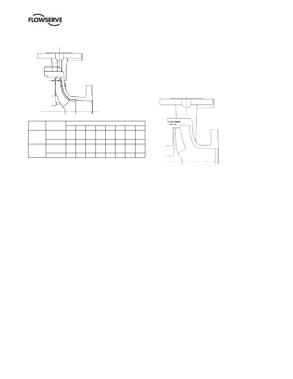
5.2.2 Setting rear clearance on ISO-M reverse
vane impeller (RV)
Clearance settings:
Impeller
diameter
Motor frame size
80
90 100 112 132 160 180 200
Up to
210 mm
Clearance
(mm)
0.3 0.3 0.3 0.3 0.3 0.3 0.3 0.3
Notches
7
7
7
7
7
8
8
8
211 to
315 mm
Clearance
(mm)
0.4 0.4 0.4 0.4 0.4 0.4 0.4 0.4
Notches
8
8
8
8
8
9
9
9
Reverse vane impellers are set off the cover [1220].
This allows the impeller [2200] to be set without the
casing [1100].
a) Disconnect the muff coupling [7120] and clean up
the bores.
b) Clean motor shaft and stub shaft and deburr
where necessary.
c) Replace muff coupling [7120], ensuring that the
grub screw locates in the stub shaft.
d) The motor end coupling bolts [6570.2] should be
slacker than the pump end coupling bolts
[6570.4] so that the coupling and stub shaft can
be rotated relative to the motor shaft.
e) The motor shaft should be prevented from
rotating by using a C-spanner located in the
keyway (where possible) or by locking the fan
end of the motor [8100].
f) With the casing [1100] removed, rotate the
coupling [7120] until the impeller contacts the
cover [1220]. This is the zero clearance position
or datum for setting the rear clearance.
g) Mark the bracket with a pen and, whilst preventing
the motor shaft rotating, turn the coupling [7120] in
the opposite direction by the recommended
number of notches as indicated in the table. For
the remaining steps, take care not to rotate the
pump shaft relative to the motor shaft.
h) Carefully loosen and back off the grub screw and
tighten the coupling bolts [6570.4], ensuring that the
gap is equal between the coupling halves [7120].
i)
Torque the screws to the specified values:
M8
– 30 Nm (22 lbf•ft)
M10
– 58 Nm (43 lbf•ft)
j)
Push the impeller [2200] axially towards the cover
[1220] to close the motor bearing axial play.
k) Ensure the impeller rear clearance is as indicated
in the table using a feeler gauge.
l)
Check that the shaft can turn freely without
binding.
m) If a cartridge seal is fitted it should be reset at this
point.
5.2.3 Setting rear clearance on ISO-RM recessed
impeller
Recessed open impellers are set off the cover [1220].
This allows the impeller [2200] to be set without the
casing [1100].
a) Disconnect the muff coupling [7120] and clean up
the bores. Ensure the casing [1100] is not fitted.
b) Clean motor shaft and stub shaft and deburr
where necessary.
c) Replace muff coupling [7120], ensuring that the
grub screw locates in the stub shaft.
d) The motor end coupling bolts [6570.2] should be
slacker than the pump end coupling bolts
[6570.4] so that the coupling and stub shaft can
be rotated relative to the motor shaft.
e) The motor shaft should be prevented from
rotating by using a C-spanner located in the
keyway (where possible) or by locking the fan
end of the motor [8100].
f) With the casing [1100] removed, rotate the
coupling [7120] until the rear clearance is 1.5 to 2
mm (0.06 to 0.08 in) as illustrated. This is the
setting position. For the remaining steps, take
care not to rotate the pump shaft relative to the
motor shaft.
g) Carefully loosen and back off the grub screw and
tighten the coupling bolts [6570.4], ensuring that the
gap is equal between the coupling halves [7120].
h) Torque the screws to the specified values:
M8
– 30 Nm (22 lbf•ft)
M10
– 58 Nm (43 lbf•ft)
i)
Check that the shaft can turn freely without binding.
j)
If a cartridge seal is fitted it should be reset at this
point.