9 assembly – Flowserve ERPN-M User Manual
Page 29
ERPN-M USER INSTRUCTIONS ENGLISH 02-08
Page 29 of 37
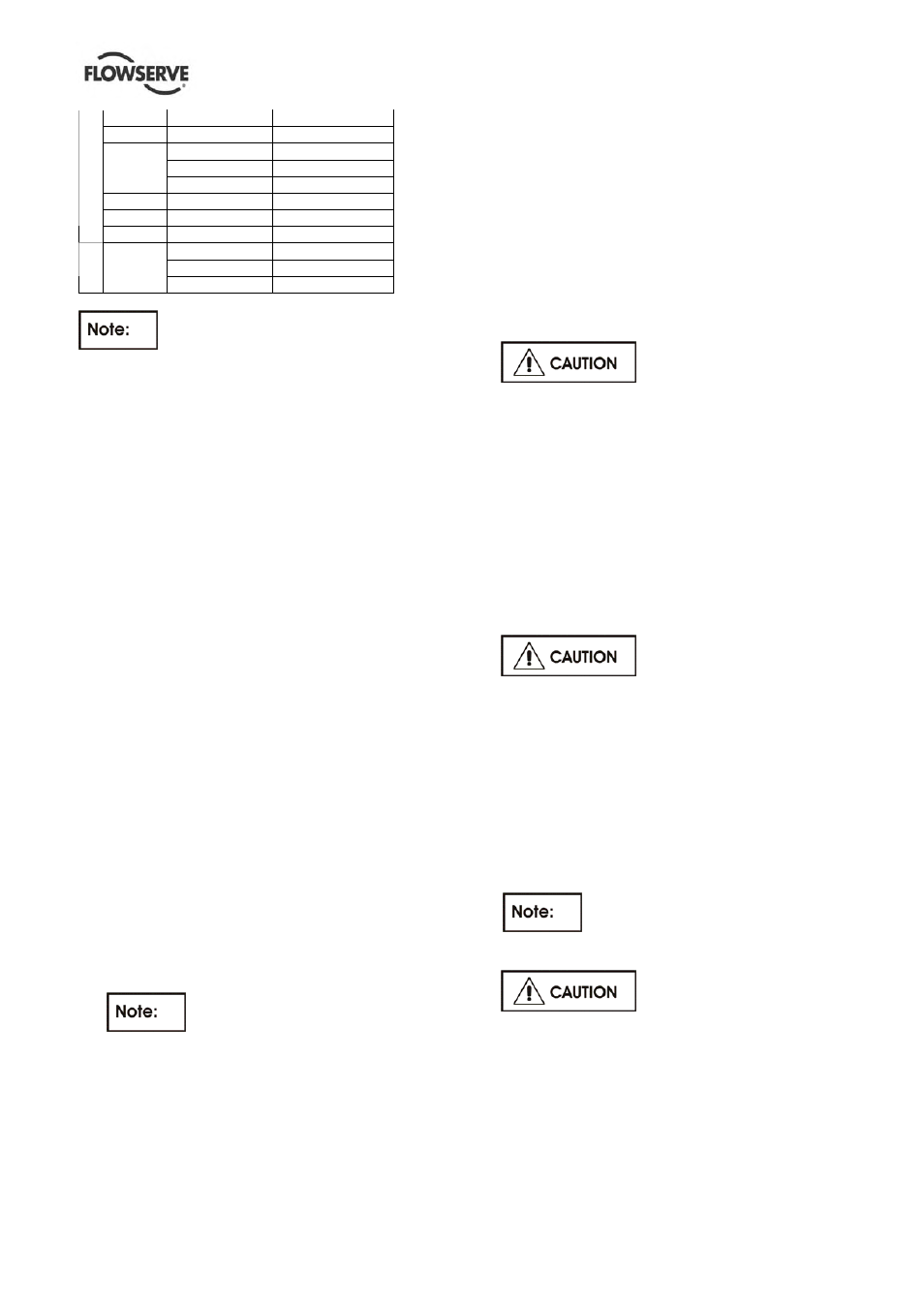
100-400 184 (7.2)
0.35 (0.014)
150-400 225 (8.9)
0.4 (0.016)
150-504 225 (8.9)
0.4 (0.016)
200-315 235 (9.3)
0.4 (0.016)
200-400 235 (9.3)
0.4 (0.016)
200-504 256 (10.1)
0.4 (0.016)
250-404 265 (10.4)
0.4 (0.016)
FRAME 5
250-504 300 (11.8)
0.4 (0.016)
150-604 225 (8.9)
0.4 (0.016)
200-604 256 (10.1)
0.4 (0.016)
FR. 6
250-604 300 (11.8)
0.4 (0.016)
Gaps apply approximately for wear rings
in all materials and in assembled condition.
6.8.2 Gap at free flow impeller – ERPN-M – F
Diametrical gap between vane on the back of impeller
[425] and casing cover [370] in assembled condition:
1 mm [0.04 in.].
Diametrical gap between vane on the front of impeller
[425] and pump casing [360] depends on the width of
pump casing spiral as impeller is located outside and
a quarter of width of impeller outlet extend into spiral
at most.
6.8.3 Gap at open impeller – ERPN-M – O
Diametrical gap between vane on the back of impeller
[425] and casing cover [370] in assembled condition:
1 mm [0.04 in.].
Diametrical gap between vane on the front of impeller
and pump casing [360] in assembled condition: 1mm
[0.04 in.].
6.9 Assembly
To assemble the pump consult the sectional
drawings, see section 8, Parts list and drawings.
Ensure threads, gasket and O-ring mating faces are
clean. Apply thread sealant to non-face sealing pipe
thread fittings.
6.9.1 Assembly of the inner rotor
1) Slip on the casing cover [370] and insert key
[416] into the keyway. Slip on impeller [425] and
locking plate [4549 to the shaft [415]. Fasten the
impeller with the impeller nut [456] and secure it
with the locking plate [454].
Pumps having a screwed inducer,
have no impeller nut. Therefore fasten the
impeller with the inducer. Pumps having a slipped
on inducer are fastened by using the socket
screw [456].
2) Put the axial bearing [M05] on impeller shaft [417]
so that it touches the shaft shoulder. The cylindrical
pin [4173] previously fixed on impeller shaft [417]
must fit into the corresponding hub.
3) Now fix radial bearing [M04] on casing cover [370]
by socket screws [041] so that longitudinal groove
of inner diameter lies approximately in horizontal
line (vertically to resulting radial forces).
Arrangement of screws allow that the bearing can
only be mounted in this position.
4) Put shaft sleeve [M07] on impeller shaft [417].
Alignment of the axial bearing [M05] happens
simultaneously.
5) Put the key [418] into shaft groove and push axial
bearing [M06] on impeller shaft [417] where it is
fixed and secured by a washer [4172] and a hex
screw [4171].
Prestress bearing parts always
in a vertical shaft position. Turn torque constantly
and uninterruptedly. Beats are prohibited. The
impeller shaft should turn easily when supported at
casing cover [370].
6) Now push inner rotor [M01] of magnetic coupling
on axial bearing [M06]. The two cylindrical pins
[M09] have to gear into the corresponding bores for
guidance.
7) Fix the inner rotor [M01] by socket screws
[M08].Secure these screws by Loctite.
8) Put new gasket [507] into casing cover [370].
Push can [M03] over the inner rotor [M01] and
screw it on casing cover [370] by socket screws
[043].
Pay attention to circulation
bores which ensure an automatically vent and
outflow by a free flow.
After all above mentioned steps lift complete
driver unit into pump casing [360] and fix it by
socket screws [042]. Pay attention that there is a
new O-ring [398] in pump casing. Pay attention to
correct position of casing cover [370] to pump
casing [360] for assembling, too.
9) Put gasket [398] into the foreseen groove of
pump casing [360]. Now lift the complete "back-
pull out" assembly by crane and push it into the
pump casing [360].
The casing gasket [398] shall be
renewed after each disassembly.
10) Fasten crosswise the socket screws [042].
Take care that the pump
casing cover can [370] is connected to the pump
casing [360] in correct position.
6.9.2 Assembly of the outer rotor
1) Heat up the angular contact bearings [477] and
push it on the shaft [415] as shown in the section
drawing. Put on locking plate [464] and fix the
thrust bearing with the shaft nut [463] and secure
it by the locking plate.