0 disassembly – Flowserve Swing Check Valves 2.5-24 User Manual
Page 14
Swing Check Valves FCD ADENIM0013-00
13
5.0
DISASSEMBLY
(Continued)
5.1.2
Disc Assembly
Three methods of supporting the disc assembly in the body have been used by Anchor/Darling.
A. Hinge rotates on pin inserted through body wall (Fig. 9).
B. Hinge rotates on pin mounted in bracket hung from bonnet (Fig. 14).
C. Hinge rotates on pin supported in bracket mounted on pads above seat ring (Fig 15).
(Fig. 15) is the design currently supplied by Anchor/Darling.
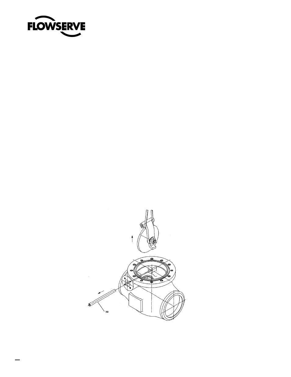
5.1.2.1 Configuration A (Figure 9)
Removal of the disc assembly in this design, necessitates withdrawing the hinge pin (5) from
side of body. The hinge pin is retained in the body by one of three methods. The hinge pin
cover in each of the designs is used to seal the penetration of the body.
A. Pipe plug threaded into body and sealed by either an asbestos or spiral wound gasket.
B. Pressure seal joint.
C. Blind flange attached to body by studs and sealed with a spiral wound gasket or seal
welded.
Prior to withdrawing the hinge pin in this configuration, make sure the hinge/disc assembly is
properly supported either by hand or with slings and that the weight of the assembly is not on
the hinge pin.
FIGURE 9