Figure 3: compliance voltage 520 – Flowserve 510si Series Digital Positioner User Manual
Page 7
7
®
User Instructions Logix 510si - LGENIM0510-0
2 12/13
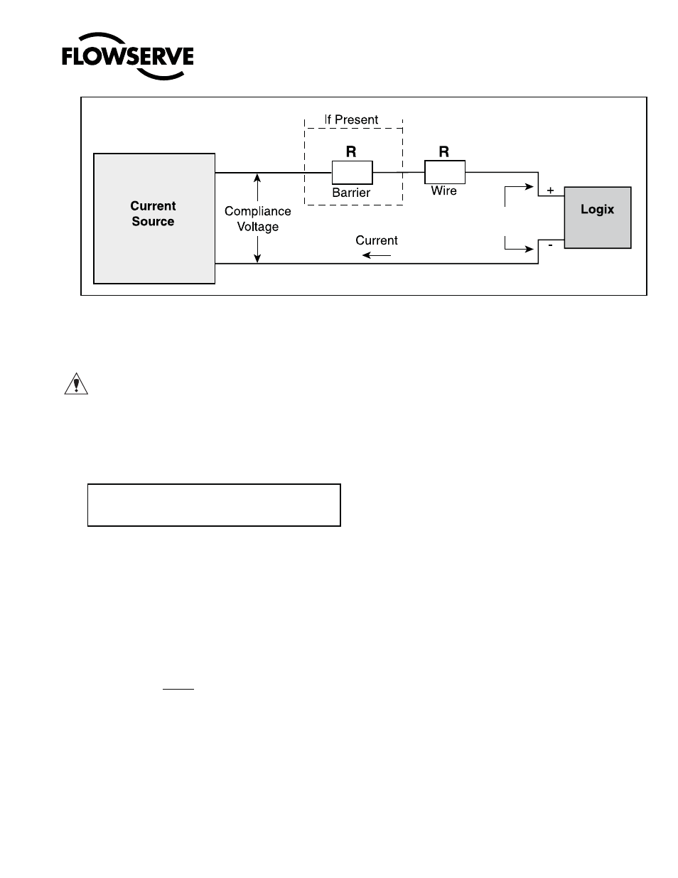
The Logix 510si requires that the current loop system
allow for a 6,0 VDC drop across the positioner at maxi-
mum loop current.
CAUTION: Never connect a voltage source directly
across the positioner terminals. This could cause per-
manent circuit board damage.
In order to determine if the loop will support the Logix
510si, perform the following calculation:
Available Voltage = Controller Voltage (@Current
MAX
)
- Current
MAX
*(R
barrier
+ R
wire
)
The calculated available voltage must be greater than
6.0 VDC in order to support the Logix 510si.
Example: DCS Controller Voltage = 19 V
R
barrier
= 300
R
wire
= 25
CURRENT
MAX
= 20 mA
Voltage = 19 V - 0,020 A*(300
+ 25 )
= 12,5 V
The available voltage 12,5 V is greater than the required
6.0 V; therefore, this system will support the Logix
510si. The Logix 510si has an input resistance equivalent
to 300
at a 20 mA input current.
The Logix 510si digital positioner has been designed to
operate correctly in electromagnetic (EM) fields found
in typical industrial environments. Care should be taken
to prevent the positioner from being used in environ-
ments with excessively high EM field strengths (greater
than 10 V/m). Portable EM devices such as hand-held
two-way radios should not be used within 30 cm of the
device.
Ensure proper wiring and shielding techniques of the
control lines, and route control lines away from elec-
tromagnetic sources that may cause unwanted noise.
An electromagnetic line filter can be used to further
eliminate noise (FLOWSERVE Part Number 10156843).
In the event of a severe electrostatic discharge near the
positioner, the device should be inspected to ensure
correct operability. It may be necessary to recalibrate
the Logix 510si positioner to restore operation.
8 STARTUP
8.1
Logix 510si Local Interface Operation
The Logix 510si local user interface allows the user
to fully configure the operation of the positioner, tune
the response, and calibrate the positioner. The Local
interface consists of a quick calibration button for
automatic zero and span setting, along with two jog
buttons for manually spanning the positioner, or for
local Jogging of the valve. There is also a switch block
containing 8 switches. Five of the switches are for basic
configuration settings, three are for calibration options
There is also a rotary selector switch for adjusting the
positioner gain settings. A 4-20 current loop calibration
button is accessed through a hole in the cover next to
the bottom dipswitch. For indication of the operational
status or alarm conditions there are 3 LEDs on the local
user interface. This document describes the setting and
use of the Logix 510si user interface.
8.2
Initial DIP Switch Setting
Before placing the unit in service, set the dipswitches in
the Configuration and Cal boxes to the desired control
options. For a detailed description of each dipswitch
setting, see sections below.
Figure 3: Compliance Voltage
520
12.0 VDC
6V