Flowserve XL Series High-Performance Positioner User Manual
Page 3
45-3
Flowserve Corporation, Valtek Control Products, Tel. USA 801 489 8611
Roller
Bearing
Cam
Start
Position
Cam
Follower Arm
NOTE: When retrofitting the XL positioner to an
actuator equipped with other positioners, remove
the existing positioner, tubing and associated bolt-
ing. See tubing instructions in Step 10.
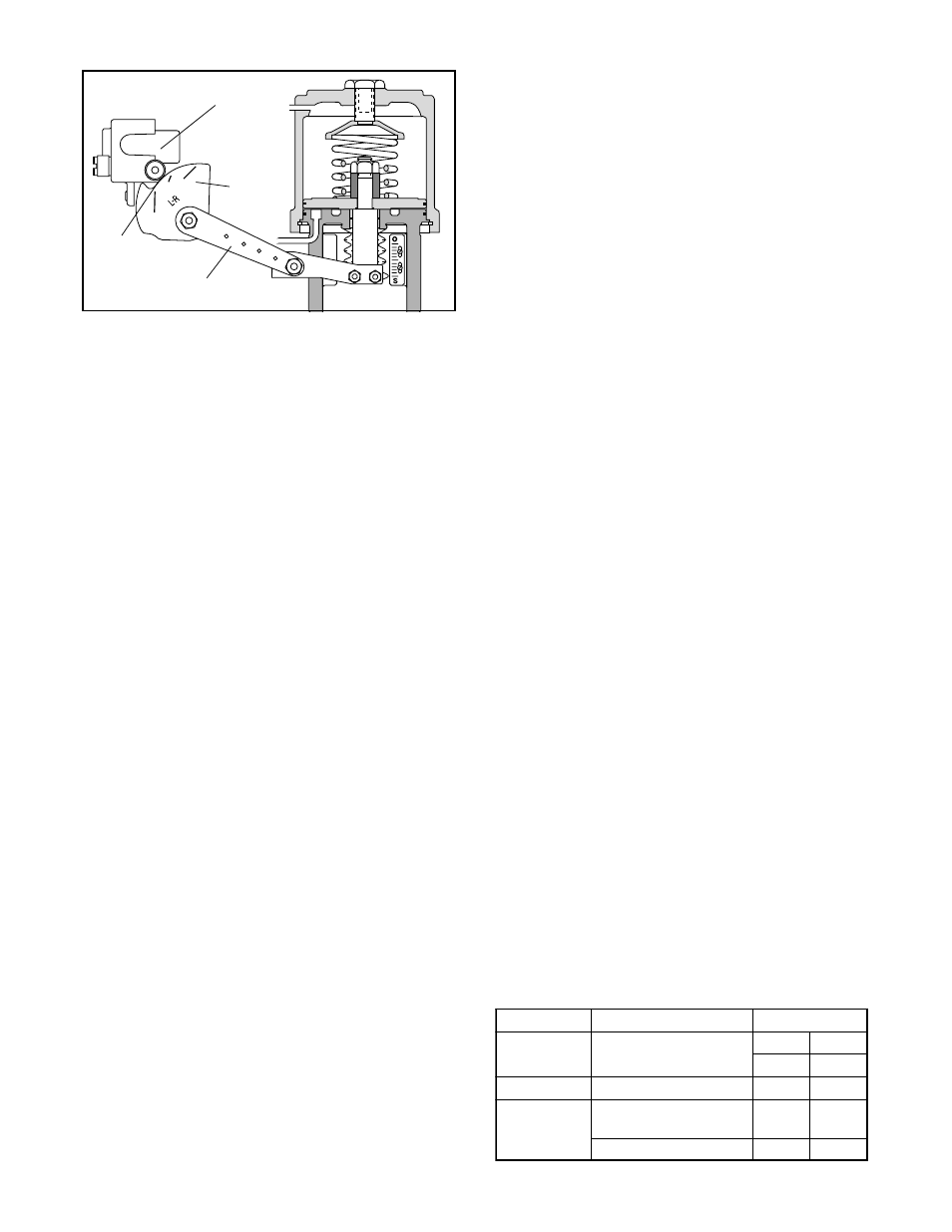
1. Place the stem clamp onto the actuator stem with
the boss on the right side as illustrated in Figure 1.
2. Mount positioner bracket to the yoke leg which has
the stroke indicator plate attached. (See Figure 2.)
3. Mount the take-off arm on the stem clamp so the
slots in the end of the arm step upward toward the
cylinder. The holes in the follower arm should line
up with the slots in the take-off arm.
4. For air-to-retract action, install the cam in the posi-
tioner, with L-R facing outward. For air-to-extend
action, L-D side of the cam should face outward.
When installing the cam, position it so the center
mark on the cam lines up through the center of the
cam roller-bearing on the cam follower arm with the
follower arm perpendicular to the base of the posi-
tioner. (See Figures 3 and 4.) Apply a small amount
of grease to the bent end of the return spring and
feed it through the hole in the cam. Loop the other
end of the return spring over the screw and screw it
into the positioner base.
NOTE: Screw head will not bottom out.
5. Feed the appropriate follower arm onto the cam
shaft boss with the hole markings facing outward.
Secure with the lockwasher and nut. (See Figure 7.)
6. Fasten the follower pin into the correct hole in the
follower arm for the desired stroke length of the trim.
(Stroke lengths are stamped on the follower arm.)
7. Feed the follower pin into the appropriate slot in the
take-off arm. (See Figure 4.) Tighten the nut on the
pin and grease the slot where the pin rides.
NOTE: A light industrial grease is recom-
mended. Failure to lubricate the pin can cause
premature wear.
8. Using three screws, mount the positioner to the
brackets as shown in Figure 2.
9. If necessary, adjust the height of the stem clamp so
the first line of the cam aligns with the center of the
cam roller-bearing when the valve is seated. (See
Figure 4.) Tighten the stem clamp.
10. For air-to-open action, tube ‘output 2’ to the top of
cylinder and ‘output 1’ to the bottom of cylinder. For
air-to-close action, tube ‘output 1’ to top of cylinder
and ‘output 2’ to the bottom of the cylinder.
NOTE: For three-way diaphragm actuators plug
output 2, tube output 1 to desired side of
diaphragm.
11. Attach supply air and instrument tubing or wiring.
CAUTION: Signal air pressure higher than 30
psi may damage the module gauge and instru-
ment signal capsule; a 3-15 psi instrument sig-
nal is recommended on the pneumatic module.
Reversing Air Action of XL Series
Positioners on Linear Actuators
Reversing the air-action of the positioner is simple. No
additional parts are required, although the tubing will
need to be rerouted on the linear actuator.
To reverse the air-action of XL series positioners on all
sizes of linear actuators, proceed as follows:
1. Using the ‘Spring Cylinder Linear Actuators’ Instal-
lation, Operation, Maintenance Instructions, reverse
the air-action of the actuator.
2. Disengage the return spring from the cam and
remove the cam from the cam shaft.
3. Reverse the cam, return spring and tubing for the
desired air-action by referring to Steps 4-8 in the
‘Installation of XL Series Positioner on Linear Ac-
tuators’ section of these instructions.
Installing XL Series Positioner on Rotary
Actuators
Proceed as follows when installing the XL Series posi-
tioner on all sizes of rotary actuators if the cam and
follower arm are not already installed, otherwise refer
directly to step 7.
1. With the desired cam and its identification letter
facing toward the cam shaft, slide the cam onto the
end of the cam shaft with the shorter shoulder. (Refer
to Table I to determine desired cam characteristic.)
Fasten with the star lock washer and nut.
2. Insert the follower arm into the back recess of the
Figure 4: Cam Alignment
Table I:
Rotary Actuator Cam Characteristic Chart
e
l
y
t
S
e
v
l
a
V
c
i
t
s
i
r
e
t
c
a
r
a
h
C
o
T
r
i
A
D
L
V
/
T
S
S
l
a
u
q
E
d
e
i
f
i
d
o
M
e
g
a
t
n
e
c
r
e
P
n
e
p
O
e
s
o
l
C
B
C
D
L
V
/
T
S
S
r
a
e
n
i
L
C
B
o
l
F
x
a
M
l
a
u
q
E
d
e
i
f
i
d
o
M
e
g
a
t
n
e
c
r
e
P
1
M
A
C
2
M
A
C
r
a
e
n
i
L
1
M
A
C
2
M
A
C