Flowserve XL Series High-Performance Positioner User Manual
Page 5
45-5
Flowserve Corporation, Valtek Control Products, Tel. USA 801 489 8611
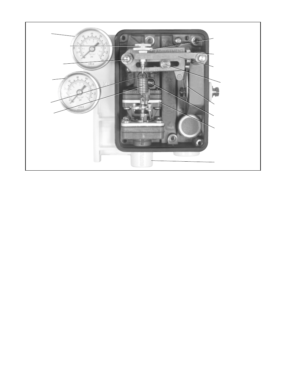
Output 1
Zero Adjustment
Lock Knob
Cam Follower
Arm (Range Arm)
Output 2
Balance
Adjusting
Screw
Feedback
Spring
reads approximately 70 psig. The average of these two
pressures is 77.5 percent of the supply pressure.
If necessary, adjust the output pressure level using the
following the procedure:
1. If output pressure level is low, before adjusting, check
for leaks in tubing connections between the posi-
tioner and actuator and check supply pressure.
2. Make certain there is no process force or pressure
in the valve (The valve should be removed or
isolated from the process.)
3. On positioners without gauges, connect gauges to
‘output 1’ and ‘output 2’ lines.
4. Remove rubber cap over balance adjustment. (See
Figure 7.)
5. Apply full actuator operating pressure to the posi-
tioner supply port.
6. Set input signal to midscale (9 psi for 3-15 psi
span). Output pressure level cannot be adjusted
with actuator against valve seat or travel stops.
Allow actuator pressure to stabilize.
7. Observe the pressure gauges. If reading is not
correct, turn balance adjustment screw about
1
/
8
turn at a time and wait about 20-30 seconds for
pressure to stabilize (counterclockwise to increase
pressure). Continue until output pressure level of
the higher pressure gauge is approximately 80
percent of supply.
8. Replace rubber cap over balance adjustment screw.
3. With a Phillips screwdriver adjust span adjustment
so valve is at full stroke with more than 15 psi for 3-15
or 9-15 psi range (adjust to 9 psi for 3-9 psi range).
4. Return to 3 psi (or 9 psi for 9-15 psi range) and
check the zero. Repeat steps 1-4 if necessary.
5. Tighten the zero adjustment lock knob and span
adjustment lock knob.
6. Use the same procedure for three-way split range.
Positioner Balance Adjustment
CAUTION: Balance is preset at the factory. If bal-
ance adjustment becomes necessary, make changes
carefully and slowly, allowing the positioner to re-
spond before continuing adjustments. Check bal-
ance pressure frequently to ensure correct values.
Balance adjustment is set at the factory and normally
should not need adjustment. Balance adjustment (out-
put pressure level) permits the equilibrium pressure in
both sides of the actuator piston to be raised or lowered.
The actuator pressure level of output 1 and 2 should be
approximately 75 to 80 percent of the supply pressure.
When actuator springs are used there will be a pressure
difference between output 1 and 2; the average pres-
sure of both ports should be 75 to 80 percent of the
supply pressure. The minimum recommended supply
pressure is 60 psig.
For example, if 100 psig supply
pressure was used on a fail closed actuator, the bal-
ance pressure should be adjusted so that output 1
reads approximately 85 psig and output pressure 2
Figure 7: Positioner Adjustments
Zero Adjustment
Knob
Span Adjustment
Feedback Spring
Arm
Span
Adjustment
Locking Screw
Cam
Orifice Screw
Pilot Relay
Assembly
Supply Port