Flowserve 020000 Series Kämmer Split Body Valves User Manual
Page 7
7
Flow Control Division
Kammer Control Valves
6.4.3 Unscrew the coupling insert until the yoke rods are
raised from the lower yoke plate by around 2 mm.
CAUTION: Ensure that the plug assembly is not rotated
with the plug seated. This may cause irreparable
damage to the seating faces.
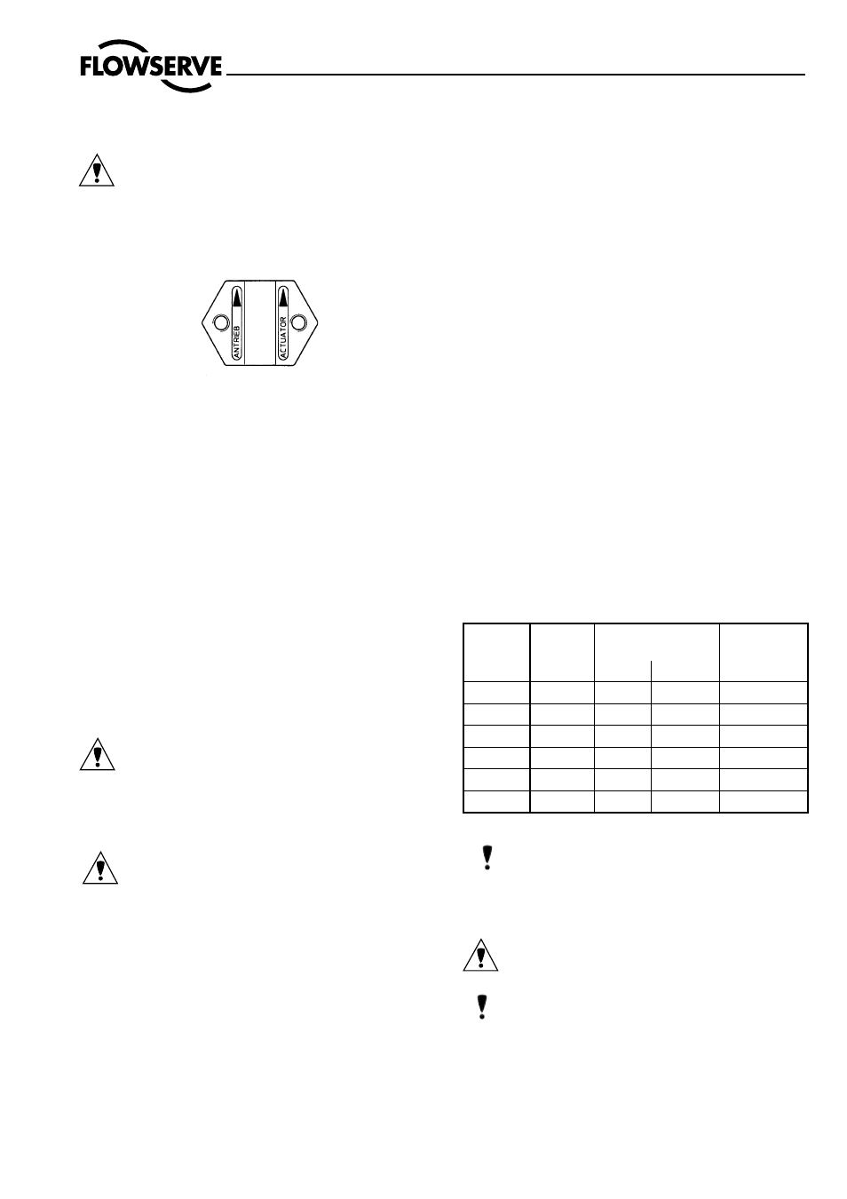
6.4.4 Refit the coupling, ensuring that the arrows, embossed
on the coupling halves, point upward towards the
actuator, and secure with 2 retaining screws.
6.4.5 Apply supply pressure resp. vent actuator to half stroke
and refit and tighten yoke rod retaining nuts (15).
6.4.6 Connect all tubing.
7
DISASSEMBLE AND ASSEMBLE VALVE
7.1
Disassemble Valve
(see Fig. 2)
7.1.1 Remove actuator according to section 3.
7.1.2 Remove housing bolts. Remove upper body with
plug.
7.1.3 Carefully press plug stem evenly out of the housing
upper part.
7.1.4 Insert two screwdrivers in outer groove of seat ring
and carefully lever seat ring out of lower body.
7.1.5 Check seating faces of seat ring and plug for damage.
Gasket surfaces must be clean and free of damage.
7.1.6 Press guides, packing and packing follower from be-
low using a drift (the drift must have a slightly larger
diameter than the plug stem).
CAUTION: To prevent damage to the plug, seat or plug
stem, follow the above instructions precisely.
7.1.7 If a seat surfaces need re-machining, seat and plug
seating surfaces must be reworked. The seat angle
on the plug is 30°, on the seat ring 25°. If the valve
is correctly assembled, lapping is not required.
CAUTION: When re-machining the plug, protect
plug stem from damage. The seat surface must be
concentric to the plug stem. When re-finishing the
seat, the seat surface must be concentric to the seat
outer diameter.
7.2
Assemble Valve
(see Fig. 2)
7.2.1 All worn or damaged parts must be replaced. Reus-
able parts must be clean. Expendable parts such
as gaskets, packing and O-rings should always be
replaced.
7.2.2 Insert seat ring in lower body, using new gaskets.
DANGER: It is most important to ensure that the
sealing rings are fitted and properly seated. The seat
and body halves are the primary metal-to-metal seal
so if the seal rings are omitted initial leak testing can
misleadingly indicate a leak-free operation. Without
sealing rings almost certainly seat leakage will occur
when the valve is in full operation.
7.2.3 Carefully guide plug stem through upper housing, to
avoid damage.
7.2.4 Position upper body on lower body carefully and ab-
solutely upright, to avoid damage to the seat/plug.
7.2.5 Insert housing bolts and tighten alternating crosswise
finger-tight.
7.2.6 Insert lower stem bushing of the packing set in the
packing area, to give better guidance to the plug stem
when tightening the body halves.
7.2.7 Tighten body bolts alternating crosswise hand-tight,
while repeatedly moving the plug stem too and fro,
in order to check whether the plug is jammed in the
seat.
7.2.8 Using a torque wrench, gradually tighten the body
bolts to the prescribed torques (see following table),
alternating crosswise.
Note:
While the body bolts are being tightened,
the body halves must always be parallel (see Fig. 3)
7.2.9 Replace packing by inserting packing rings one at a
time tapping each one down with a suitable bush-
ing.
CAUTION: ensure that the gaps in the packing rings
are distibuted evenly around the circumferance in the
packing box (gaps not in line).
Note: different packings and fitting sequences are
shown in the spare parts list.
7.10
Insert packing follower. Fit gland nut for transport
purposes only. Gland nut to be fitted correctly and
tightened down when actuator is mounted.
Thread
Hex. bolt
DIN 933
A2-70
Waisted stud
DIN 2510
Stud
DIN 939
1.7709
1.7258
CK 35
M 8
20 Nm
–
–
–
M 10
35 Nm
–
–
20 Nm
M 12
60 Nm
44 Nm
36 Nm
35 Nm
M 16
145 Nm
115 Nm
92 Nm
80 Nm
M 20
280 Nm
–
–
–
M 24
250 Nm
–
–
270 Nm