Caution – Flowserve ACE Series Centura User Manual
Page 2
©
2004, Flowserve Corporation, Printed in U.S.A.
3-Position Control/Dribble Control
SR Limit Switch Method
Accord Controls
Installation, Operation and Maintenance Instructions
Flowserve Corporation
1350 N. Mountain Springs Parkway
Phone: 801 489-2234
Flow Control Division
Springville, Utah 84663-3004
Facsimile: 801 489-2228
www.flowserve.com
10. To adjust closed position, repeat step 9 with actuator in
desired closed position.
11. Operate the unit several times and recheck position.
If unit is still out of adjustment, reset the
cams by following steps 9 and 10.
12. Installation in hazardous areas requires that the
electrical leads be sealed within 18 inches of the
enclosure in accordance with Local and National
Electrical Codes.
13. Open conduit entries must be closed up after
installation is complete using a close-up plug engaging
at least five full threads and approved for use in
hazardous locations.
14. 60Hz actuator motors may be run on 50 Hz supply.
However, the cycle time increases by 1.2 times and the
duty cycle decreases by a factor of approximately 25%.
The rated torque does not change.
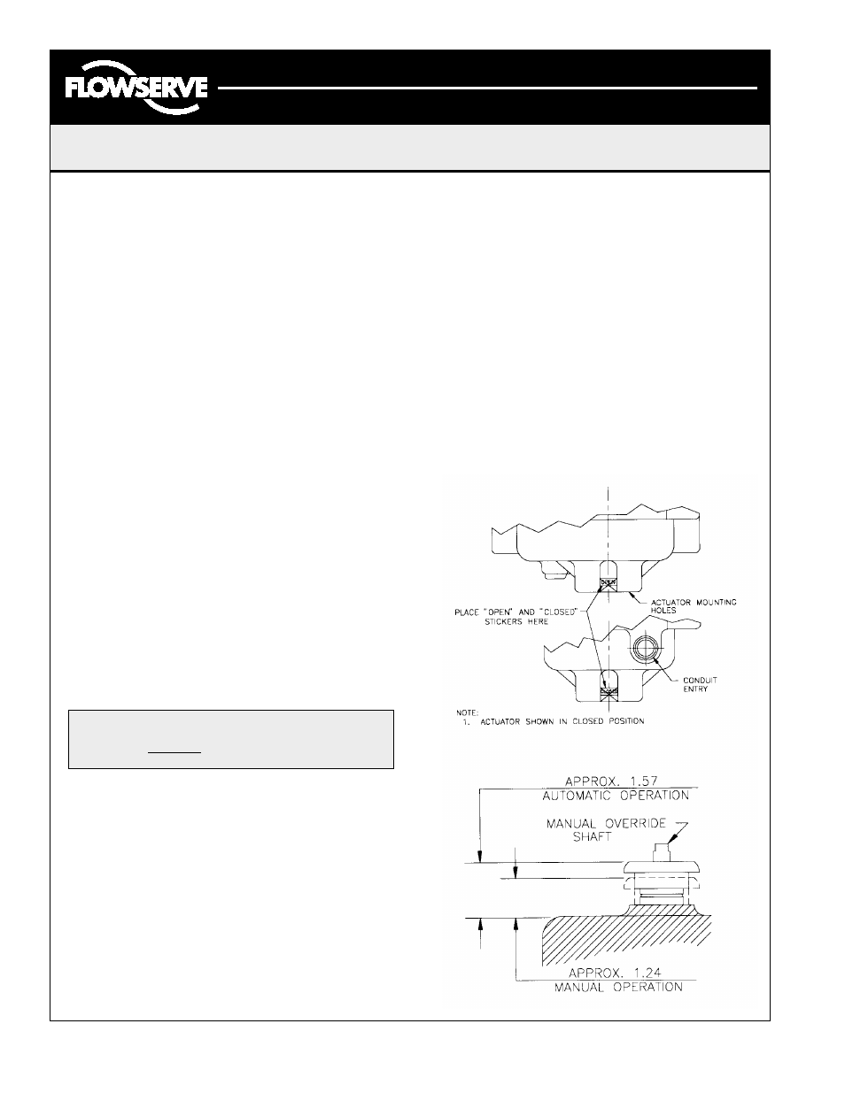
Manual Override
The principle of the design is such that when the manual
override shaft is in the up position, the shaft is disconnected
from the drive train. When the shaft is in the down position
it does two things. One, the shaft trips a switch to discon-
nect the power to the motor and two, it releases the brake.
By releasing the brake the motor can back drive along with
the output. For 90 degree operation, the 250 in-lbs unit
requires 1.6; the 700 in-lbs unit requires 3.1; the 1000 in-lbs
unit requires 4.2; and 1500 in-lbs unit requires 6.3.
Manual Operation
1.
The actuator cover should be securely attached.
2.
Depress hub toward actuator cover.
3.
Rotate the manual override shaft slowly; do not force.
4.
The motor is now electrically disconnected.
5.
Turn the manual override shaft clockwise for clockwise
output.
6.
Do not rotate actuator past full clockwise or counter-
clockwise position.
Caution:
Turn manual override shaft slowly.
DO NOT
jerk
.
Automatic Operation
1. Pull hub away from the actuator cover.
2. The motor is now electrically connected and ready
for automatic operation.
3. The manual override shaft will freewheel.
Position Indication Stickers:
Attached to the inside of the cover is a set of stickers
with the words “CLOSED” and “OPEN”. These stickers
are to be attached to the outside of the actuator near
the base between the mounting feet. The stickers have
an orange triangle on them, such that when properly
attached to the actuator, they will line up with the
triangle on the output shaft. A sticker can be placed on
either side of the unit to produce a visual indication of
the opened and closed position of the actuator.
FCD ACAIM0075-00 (AC-75) 08/04
Page 2 of 8