Foxconn P4M8907MA-KRS2H User Manual
Page 20
13
Chapter 2 Installation Instructions
Front Panel Connector: FP1
This motherboard includes one connector for connecting the front panel switch
and LED indicators.
Hard Disk LED Connector (HDD_LED)
The connector connects to the case
’s IDE indicator LED indicating the activity
status of IDE hard disk.
Reset Switch (RESET)
Attach the connector to the Reset switch on the front panel of the case; the
system will restart when the switch is pressed.
Power LED Connector (PLED)
Attach the connector to the power LED on the front panel of the case. The Power
LED indicates the system
’s status. When the system is in S0 status, the LED is
on. When the system is in S1 status, the LED is blink; W hen the system is in S3,
S4, S5 status, the LED is off.
Power Swith Connector (PW RBTN#)
Attach the connector to the power button of the case. Pushing this switch allows
the system to be turned on and off rather than using the power supply button.
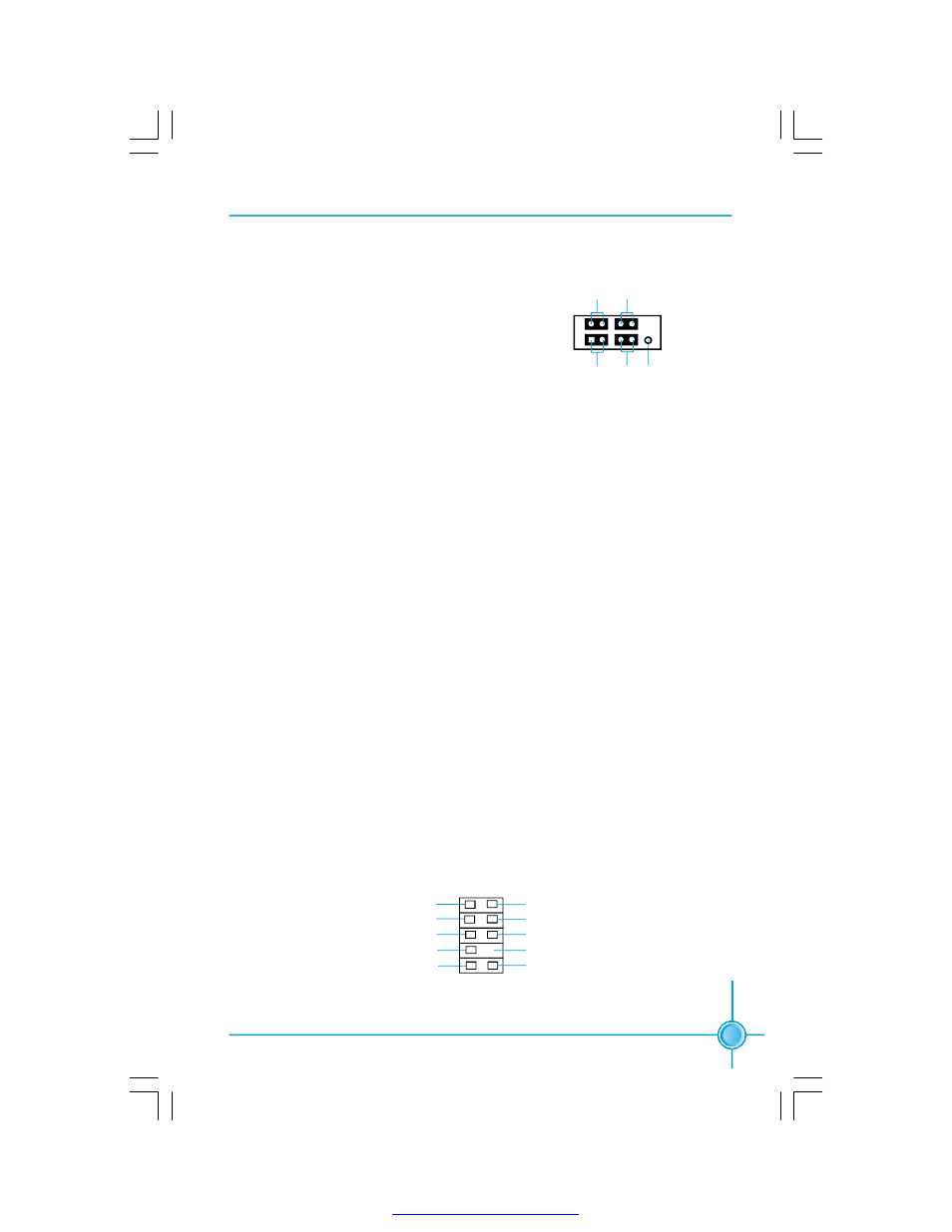
FP1
NC
HDD_LED R E S E T
PL ED P W RB T N#
1 + -
+ -
Front Audio Connector: F_AUDIO
The audio connector provides two kinds of audio output choices: the Front Audio,
the Rear Audio. Their priority is sequenced from high to low (Front Audio to Rear
Audio). If headphones are plugged into the front panel of the chassis (using the
Front Audio), then the Line-out (Rear Audio) on the rear panel will not work. If you
do not want to use the Front Audio, pin 5 and 6, pin9 and 10 must be short, and
then the signal will be sent to the rear audio port.
F_AUDIO
MIC_IN
MIC_PWR
N A
AUD_OUT_L
AUD_OUT_R
MIC_GND
+5VA
AUD_RET_R
E mpt y
AUD_RE T_ L
10
9
2
1
PDF 文件使用 "pdfFactory" 试用版本创建