Control descriptions – Fusion FM-504 User Manual
Page 3
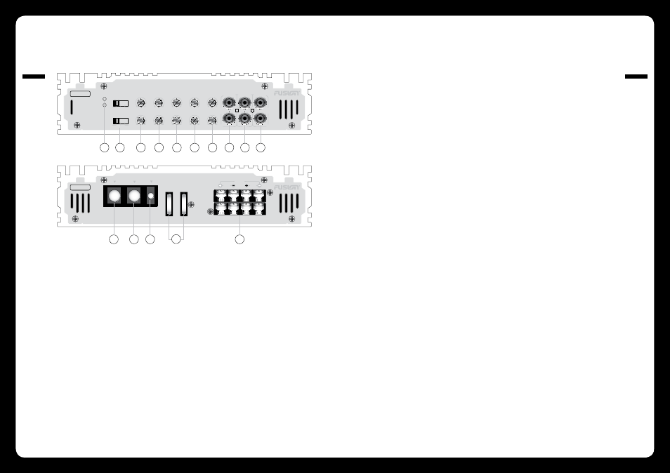
Control Descriptions
004
CONTR
OL
S
005
CONTR
OL
S
L
R
BRIDGE MODE
FUSE
FUSE
FRONT
REAR
FE-504
13
15
11
12
FUSE
FUSE
FRONT
REAR
L
R
MONO
14
20 HZ 55 HZ
8 V
0.3 V
0 DB +18 DB
40 HZ 600 HZ
40 HZ 160 HZ
LP
REM
+12V
GND
HP
LEVEL
SUBSONIC
20 HZ 55 HZ
8 V
0.3 V
0 DB +18 DB
40 HZ 600 HZ
40 HZ 160 HZ
LP
HP
LEVEL
SUBSONIC
BASS BOOST
BASS BOOST
OFF LP
HP
REAR X-OVER
SELECTOR
FRONT X-OVER
SELECTOR
OFF LP
HP
INPUT
FRONT
INPUT
REAR
OUTPUT
L
L
L
R
R
R
PWR
PRT
10
9
8
7
6
5
4
3
2
1
4 CHANNEL • FULLY REGULTED 2 OHM STABLE • Bridgeable MOSFET Amplifier
FM-504
FM-504
1 Power And Status LEDs:
this shows if the amplifier has been correctly powered up and if any faults are present.
2 Crossover Selector:
Set the appropriate mode of operation. The 3 positions available are OFF, LP and HP. See points 3 and 4 below.
3 Low Pass:
Set the crossover switch 2 to LP when a subwoofer is connected. Ensure the crossover frequency is set at
100Hz or below, this feature is designed to filter all mid to high frequencies that only FULL RANGE speakers
should produce. NOTE: Failure to do so could result in speaker damage.
4 High Pass:
Set the crossover switch 2 to HP and turn this control to 65Hz or above when using speakers smaller than 6
x 6”, this feature is designed to filter all low bass frequencies that only SUBWOOFERS should produce. NOTE:
Failure to do so could result in speaker damage.
5 Bass Boost:
This is a variable control to increase the bass boost at 45Hz from 0 -+18dB of gain, adjust to suit.
6 Subsonic Filter:
This is a variable control filters out all Sub Bass Frequencies below the set point at 18dB/octave.
7 Level:
This allows level adjustment of the input signal. Use this control to correctly match the head unit to the
amplifier. To set this control correctly, turn the amplifier level to MIN and the head unit to 3/4 volume, with
the BASS and TREBLE on zero , then slowly turn up this amplifier level control towards the MAX end of the
control. NOTE: If the sound becomes distorted, turn this control down.
8 Front RCA Input:
Connect these RCA connectors to the front LOW LEVEL output connection from the head unit.
9 Rear RCA Input:
Connect these RCA connectors to the rear LOW LEVEL output connection from the head unit.
10 RCA Output:
Use these RCA Output connectors to connect to a secondary amplifier. This output is a SUMMED OUTPUT con-
nection derived from the front RCA input and the rear RCA input connectors.
11 Ground Connection:
Connect directly to suitable ground point via a 4 gauge power cable. NOTE: This is to be the first wire to con-
nect when wiring up amplifiers. Damage could result of this is not done.
12 +12V Connection:
This must be connected to the battery positive (+) terminal via a 4 gauge power cable and with an inline fuse
or circuit breaker at the battery end. NOTE: This is to be the last wire to connect up during installation as
damage could result.
13 Remote Connection:
This input is for turning the amplifier on and off. This requires a switched positive (+12V) to power ‘ON’ the
amplifier, this can be found on the rear of the head unit in the form of an electric antenna output, or a remote
on output. If not available you can wire to the ACC position on the key.
14 Fuses:
Please ensure the correct type of fuse is fitted, as specified in this manual. PLEASE NOTE: the FM-504 has 2x
25A fuses.
15 Speaker Output:
See 4/3/2 channel installation diagrams in this manual for correct speaker connection.