Fusion FM-504 User Manual
Page 5
L
R
BRIDGE MODE
FUSE
FUSE
FRONT
REAR
FE-504
FUSE
FUSE
FRONT
REAR
L
R
MONO
20 HZ 55 HZ
8 V
0.3 V
0 DB +18 DB
40 HZ 600 HZ
40 HZ 160 HZ
LP
REM
+12V
GND
HP
LEVEL
SUBSONIC
20 HZ 55 HZ
8 V
0.3 V
0 DB +18 DB
40 HZ 600 HZ
40 HZ 160 HZ
LP
HP
LEVEL
SUBSONIC
BASS BOOST
BASS BOOST
OFF LP
HP
REAR X-OVER
SELECTOR
FRONT X-OVER
SELECTOR
OFF LP
HP
INPUT
FRONT
INPUT
REAR
OUTPUT
L
L
L
R
R
R
PWR
PRT
4 CHANNEL • FULLY REGULTED 2 OHM STABLE • Bridgeable MOSFET Amplifier
FM-504
FM-504
FUSE
PLEASE NOTE: The crossover selector positions
L
R
BRIDGE MODE
FUSE
FUSE
FRONT
REAR
FE-504
FUSE
FUSE
FRONT
REAR
L
R
MONO
20 HZ 55 HZ
8 V
0.3 V
0 DB +18 DB
40 HZ 600 HZ
40 HZ 160 HZ
LP
REM
+12V
GND
HP
LEVEL
SUBSONIC
20 HZ 55 HZ
8 V
0.3 V
0 DB +18 DB
40 HZ 600 HZ
40 HZ 160 HZ
LP
HP
LEVEL
SUBSONIC
BASS BOOST
BASS BOOST
OFF LP
HP
REAR X-OVER
SELECTOR
FRONT X-OVER
SELECTOR
OFF LP
HP
INPUT
FRONT
INPUT
REAR
OUTPUT
L
L
L
R
R
R
PWR
PRT
4 CHANNEL • FULLY REGULTED 2 OHM STABLE • Bridgeable MOSFET Amplifier
FM-504
FM-504
FUSE
FL FR
RL RR
FL
FR
RL
RR
PLEASE NOTE: The crossover selector positions
R
L
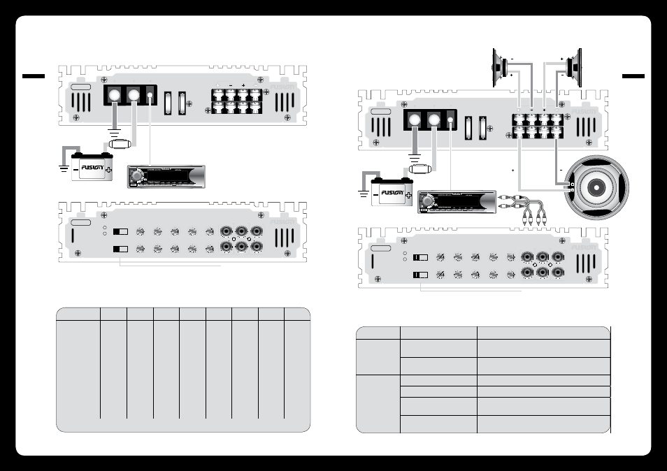
2 Channel Installation
3 Channel Installation
Power Cable Calclator
Trouble Shooting
Total Amperage
0-4ft
4-7ft
7-10ft
10-13ft
13-16ft
16-19ft
19-22ft
22-28ft
0-20
14
12
12
10
10
8
8
8
20-35
12
10
8
8
6
6
6
4
35-50
10
8
8
6
4
4
4
4
50-65
8
8
6
4
4
4
4
2
65-85
6
6
4
4
2
2
2
0
85-105
6
6
4
2
2
2
2
0
105-125
4
4
4
2
0
0
0
0
125-150
2
2
2
0
0
0
0
0
The above chart shows cable gauges to be used, if no less than a 0.5 volt drop is acceptable. If aluminium wire or tinned wire is used, the gauges should be of an even larger
size to compensate. Cable gauge size calculation takes into account terminal connection resistance. 1 Metre = 3.28 Feet
Problem
Cause
Solution
Power LED not ‘ON
Fuse at battery blown or not installed
Replace with correct fuse. Typically twice the rating of the fuse that
is on the amplifier
Improper connections
Check that the ground wire, power wire and the remote wires are
connected to the correct terminal
Status LED ‘ON’
Fuse or amplifier blown
Replace with the correct AMP rated fuse
Amplifier too hot
Move the amplifier into a more ventilated area
Speaker wires shorted
Check that there are no speaker wires shorted to any other wire and
also check if any wire is shorted to the vehicle chassis
Internal malfunction
Disconnect all wires except ground, power and remote. Then turn the
amplifier ’ON’, if the protection light is still ’ON’ then return for service
008
INST
ALLA
TION
009
CONNECTION