GAI-Tronics 12593-001 Redundant PPI Switching Module User Manual
Page 3
Pub. 42004-411A
Model 12593-001 Redundant PPI Switching Module
Page: 3 of 6
\\s_eng\gtcproddocs\standard ioms - current release\42004 instr. manuals\42004-411a.doc
05/08
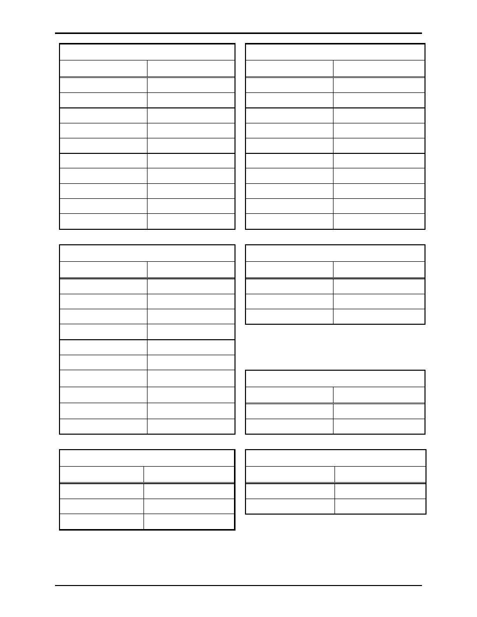
J1 – Primary PPI Card (25-pin D-Sub)
J2 – Secondary PPI Card (25-pin D-Sub)
Pin No.
Function
Pin No.
Function
1 & 2
Page Line
1 & 2
Page Line
3 & 4
Party Line 1
3 & 4
Party Line 1
5 & 6
Party Line 2
5 & 6
Party Line 2
7 & 8
Party Line 3
7 & 8
Party Line 3
9 & 10
Party Line 4
9 & 10
Party Line 4
11 & 12
Party Line 5
11 & 12
Party Line 5
13
Earth ground
13
Earth ground
15 & 17
Output control (RLY)
15 & 17
Output control (RLY)
20 & 21
Control input (CLS)
20 & 21
Control input (CLS)
14, 16, 18, 19, 22-25
Spare – No connection
14, 16, 18, 19, 22-25
Spare – No connection
J3 – Page/Party® Output (25-pin D-Sub)
JTB1 – Relay Contact Output
Pin No.
Function
Terminal No.
Function
1 & 2
Page Line
1
Normally open
3 & 4
Party Line 1
2
Common
5 & 6
Party Line 2
3
Normally closed
7 & 8
Party Line 3
9 & 10
Party Line 4
11 & 12
Party Line 5
13 Earth
ground
JTB2 - 12 V dc Power Output
15 & 17
Output control (RLY)
Terminal No.
Function
20 & 21
Control input (CLS)
1
12 V (+)
14, 16, 18, 19, 22-25
Spare – No connection
2
12 V (-)
JTB3 – 12 V dc Power Input
JTB4 – Switching Control Inputs
Terminal No.
Function
Terminal No.
Function
1
12 V (+)
1
Primary control line
2
12 V (-)
2
Secondary control line
3 GND