Installation – Guntermann & Drunck NEO-FiberLink2 User Manual
Page 8
Installation
5 · NEO-FiberLink-2
Installation
The transmitter and receiver module can either be placed between the master and
the slave matrix switch (cascade level 1) or between the slave matrix switches of the
second cascade level.
Connecting the transmitter module
(NEO-FiberLink-2Tx)
Place the transmitter module close to the slave matrix switch.
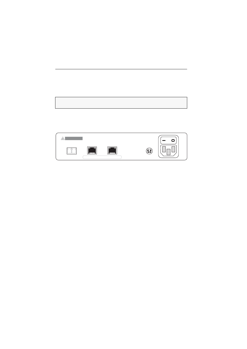
Transmission – Tx:
Insert the LC plug of the fibre optics, which is available as acces-
sory. Connect the other end of the cable to the Transmission – Rx interface of the
receiver module.
Transmission – Rx:
Insert the LC plug of the fibre optics, which is available as acces-
sory. Connect the other end of the cable to the Transmission – Tx interface of the
receiver module.
Transmission-1 CAT:
Use a CAT5 (or better) twisted pair cable to connect these inter-
faces to one of the CON interfaces of the slave matrix switch.
Transmission-2 CAT:
Use a CAT5 (or better) twisted pair cable to connect these inter-
faces to one of the CON interfaces of the slave matrix switch.
Red. Power:
If necessary, connect the connection cable of the optional power pack to
this interface. Then connect a power cable to the power pack and a power outlet.
Main Power:
Insert the supplied power cable and connect it to a power outlet.
ADVICE:
Basic information regarding the cascading of a matrix switch is given in
the chapter Installing the expansion unit of the matrix switches’ installation manual.
Transmission-2 CAT
Transmission-1 CAT
to slave / lower-level device
Main
P
ower
Red. Power
Class 1 Laser Product
Rx
Tx
Transmission Fiber