Herrtronic, Rdu-d supplement – Herrmidifier Herrtronic RDU-D User Manual
Page 4
Herrtronic
®
RDU-D Supplement
I n s t a l l a t i o n , O p e r a t i o n , & M a i n t e n a n c e M a n u a l
4
www.herrmidifier-hvac.com
As shipped, the RDU is set up for direct unit mounting.
Longer wiring and condensate return tubing (supplied) will
be required for remote mounting. Be sure to use 18 gauge
(minimum) copper conductor wire with insulation rated for
600 VAC. Supply power may originate from the Herrtronic
humidifier or a separate supply. If a separate source is
used, be sure to install a dedicated power disconnect.
All hardware and accessory components required for
installation are included as listed below:
Accessory Bag Contents
Item
Quantity
¾” I.D. Plastic bushing
2
3” Diameter plastic hole plug
2
5/16” I.D. Plastic bushing
1
Steam inlet union
1*
2 ½” Stainless steel hose clamp
1*
¼” x 2” Lag screw
2
#8–32 x 3/8” Stainless steel machine screw 4
Wiring Kit
1
¼” O.D. Condensate return tubing
10’
*-Double quantity for RDU-D-2 series units
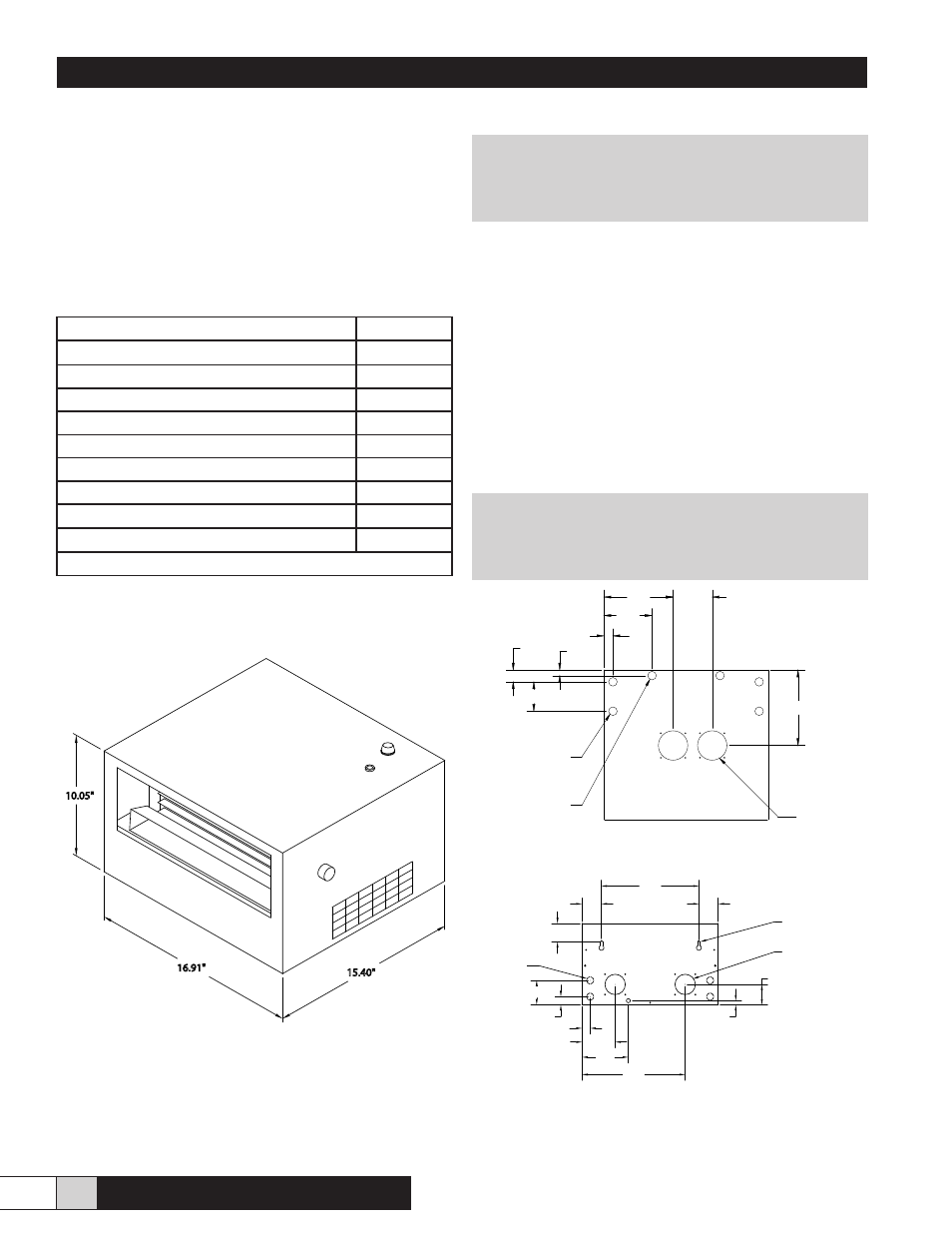
Figure 2 - Overall Dimensions
III. INSTALLATION PREPARATION
! WARNING !
Disconnect power to the humidifier while
installing RDU.
The RDU unit must either be placed higher than the
Herrtronic unit or provisions for handling the condensate
via an external drain must be made. The following chart
details the physical clearances around the cabinet for
servicing the unit. Figure 13 details the clearances required
due to the steam plume.
MINIMUM CLEARANCES AROUND CABINET
LEFT - 15”
RIGHT - 15”
TOP* - 2”
BOTTOM - 0”
* Subject to output, fan speed and room conditions
NOTE:
The steam plume should not impinge on walls,
ceilings or other objects. Supply air registers, if
present, must be directed away from RDU.
Figure 3 - Bottom View Dimensions
Figure 4 - Back View Dimensions
10.05"
16.91"
15.40"
Figure 3 Top View Dimensions
.99"
4.99"
7.13"
4.00"
7.70"
1.20"
3.00"
.56"
(4) 7/8" Holes
Power Access
(2) 7/8" Holes
Optional Condensate Drain
(2) 3" Holes
Steam Hose Inlet
Figure 4 - Bottom View
Front of Unit
2.45"
12.00"
2.45"
2.30"
(4) 7/8" Knockouts
Power Access
3.00"
1.00"
.99"
5.77"
.50"
2.50"
(2) 2 1/2" Holes
Optional Steam Inlets
(2) 5/16 X 5/8 Dia.
Keyhole Mounting Slots
Figure 5 - Back View
4.14"
12.76"