Herrtronic, Rdu-d supplement – Herrmidifier Herrtronic RDU-D User Manual
Page 5
Herrtronic
®
RDU-D Supplement
I n s t a l l a t i o n , O p e r a t i o n , & M a i n t e n a n c e M a n u a l
5
www.herrmidifier-hvac.com
REMOVE THE COVER FROM THE RDU
1. Loosen the two hex socket head set screws on the fan
speed control knob and remove knob (Figure 5).
2. Remove the phillips head screws which fasten the
cover to the housing.
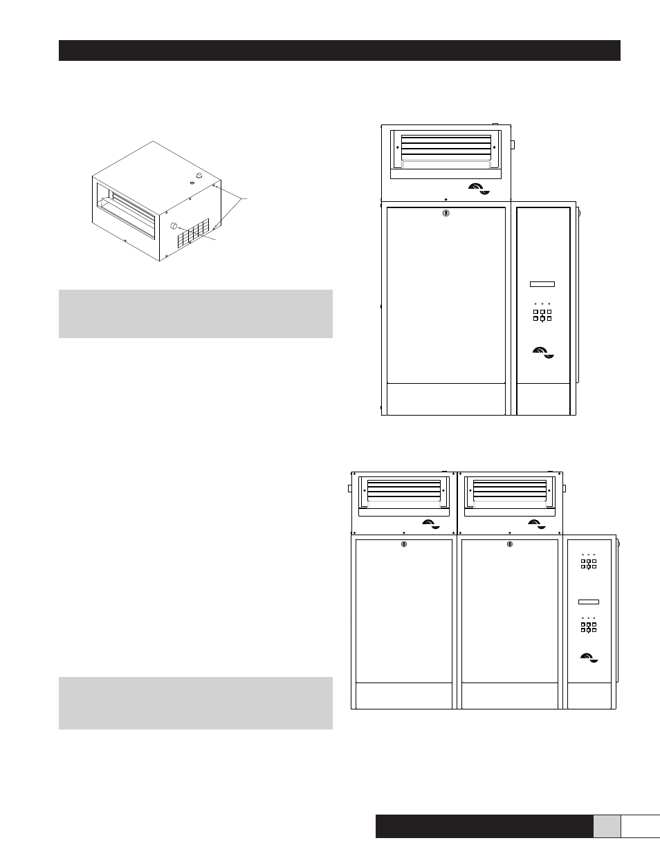
IV. DIRECT MOUNT OPTION (MDS, MDD)(Figure 6 & 7)
! WARNING!
Be sure to disconnect power to the Herrtronic
Humidifier before beginning installation.
1. Assure that the mounting for the Herrtronic unit will
support the additional 40 pound load of each RDU
unit.
2. Remove the knock-out from the top of the Herrtronic
cabinet and install the 5/16” I.D. plastic bushing for the
condensate return.
3. Remove the rearmost 7/8” knockout from the top of
the Herrtronic cabinet.
4. Install one 3/4” plasitc bushing from the inside into the
rearmost 7/8” hole in the bottom of the RDU.
5. Place the RDU on the Herrtronic cabinet, guiding the
steam hose(s) into the tank compartment.
6. Feed the wires (total of seven) through the 3/4” bushing
and condensate tubing through the 5/16” bushing into
the Herrtronic unit.
7. Fasten the RDU in place using four #8-32 self-tapping
screws installed from inside the Herrtronic cabinet.
8. Replace the RDU cover & fan speed control knob.
9. Insert the condensate return tubing into the grey
plastic fill tee. It will extend I” into the tee.
10. Connect wires # 1 -6 to the 6 pole RDU terminal strip
located near the top of the Herrtronic high voltage
electrical compartment. Connect the ground wire #24
to the Herrtronic ground terminal located near the
bottom of the high voltage compartment.
NOTE
See Figure 15, 16 & 17 for standard electrical hookup
for MDM and MDS.
11. Remove jumper wire #39 from the Herrtronic 12
pole controls terminal strip located in the low voltage
electrical compartment between poles #1 and #2.
Installation is now complete. Proceed to the RDU Operation
section of this manual then to the Start-Up section of the
Herrtronic Installation and Operation Manual OM-93.
Figure 6 - MDS Direct Mount
Figure 7 - MDD Direct Mount
ENTER
FAULTS
HERRTRONIC MD
ON/OFF
CYL FULL
BACK
FAULT
POWER
HERRMIDIFIER
HERRMIDIFIER
HERRMIDIFIER
HERRMIDIFIER
HERRMIDIFIER
SLAVE
FAULT
POWER
BACK
ENTER
FAULTS
ON/OFF
CYL FULL
MASTER
FAULT
POWER
BACK
ENTER
ON/OFF
FAULTS
CYL FULL
HERRTRONIC MD
PHILLIPS HEAD SCREWS
(6) PER SIDE
(1) ON FRONT SIDE
Fan Speed Control Knob
Figure 5