Herrmidifier Herricane CS User Manual
Page 25
Herricane CS
®
Series
I n s t a l l a t i o n , O p e r a t i o n , & M a i n t e n a n c e M a n u a l
25
www.herrmidifier-hvac.com
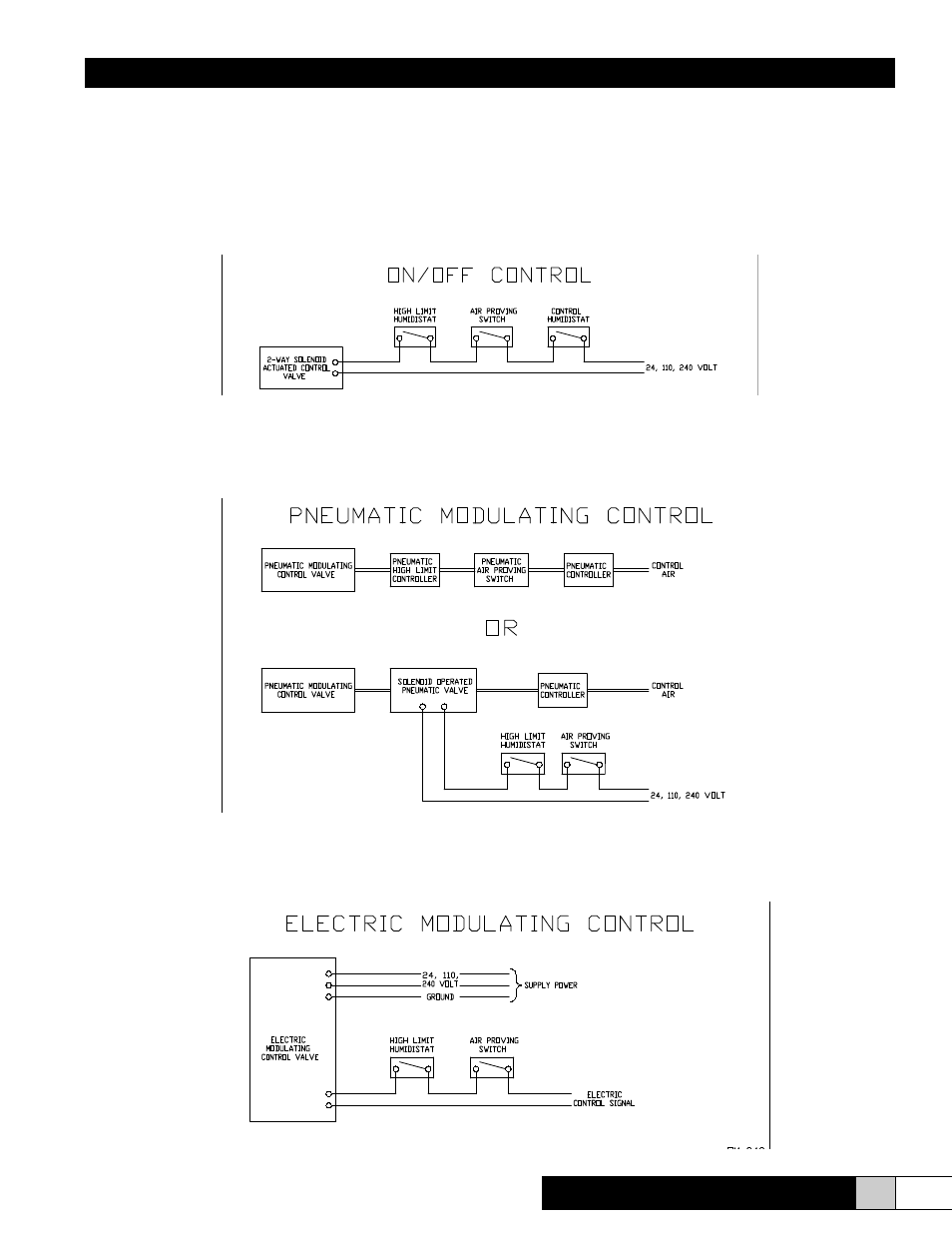
VI. CONTROL OPTIONS
On/Off Control: While the simplest to wire, on/off control is also the least accurate control scheme available. Instructions
are included with each actuator/linkage package which details the proper connections of power to the actuator. It is always
recommended that control, high limit, and air proving devices be used. In the case of on/off control, the three devices are
simply wired in series.
Pneumatic Modulating Control: As with on/off control, the proper connection methods are included in the actuator/linkage
package. Also, control, high limit, and air proving devices are recommended. With pneumatic modulating control, the high limit
and air proving devices may be pneumatic, which allows for a modulating high limit and the best possible control, or electric,
where a solenoid valve makes or brakes the pneumatic control air. The solenoid power is controlled by the on/off high limit
and air proving devices which are wired in series with the power supply to the solenoid.
Electric Modulating Control: The wiring schematic is included in the actuator/linkage package. The power supply (24 VAC,
120 VAC, or 240 VAC) and the control signal (4-20 mA, 0-10 VDC voltage signal, etc.) must be specified at the time of order.
Double check that what was ordered matches the power available prior to installing the device. High limit and air proving
devices are recommended.