Infloor Thermostat 29053 V1 User Manual
Preparation, Installation
Relout
2
3
4
5
Relin
Relin
Relout
2
3
4
5
Relin
Relin
Relout
Setback
Sensor
2
3
4
5
Relout
Relin
Relin
Relout
Relin
Relin
Relout
Connect Power Wires
1. Match and connect the
two wires marked “LINE1” and
“LINE2” to the power supply
wires using the wire nuts
provided.
2. Gently tug on the wires to
make sure they are secure,
otherwise a wire could loosen
and cause failure.
3. Overwrap the wire nuts with
electrical tape to better secure
them to the wires.
4. Match and connect the two
wires marked “LOAD1” and
“LOAD2” to the floor warming
system lead wires and secure
these wires the same way.
5. Connect the house ground wire to the green lead wire(s) of your floor
warming system.
CAUTION:
Before continuing, make sure your power supply voltage matches
the voltage rating of your floor warming system.
Connecting 240V to a 120V floor warming system will cause overheating
and damage to the system and may damage the control, other wiring, floor
coverings, etc.
29053V1 Owner’s Manual
Your new Infloor
Relay is designed to control the voltage to either a
120VAC or 240VAC resistive floor warming system. It must be driven by a
Infloor thermostat to operate.
Please follow this manual for complete installation and operation instructions.
If you have any questions or comments, try calling Technical Support at
1-800-608-0562.
Make sure you are qualified and are familiar with house wiring. This is a
line voltage device that could cause serious injury or damage if improperly
installed.
Part# 29053
1. Preparation
1. Unpack your Relay and make sure everything is in good condition:
Relay
•
Small screwdriver
•
Mounting screws
•
Wire nuts for wiring connections
•
If any parts are missing or damaged, contact the store where you purchased
this relay. Do not install a damaged part.
2. Gather the following tools and supplies:
•Phillips screwdriver, hole saw
•Wire strippers, “fish tape”, other electrical tools
•Electrical box for relay:
a. If you are connecting to power leads from only 1 or 2 floor warming
systems, you may use a single-gang, 3
1
⁄
2
inch deep box.
b. If you are connecting to power leads from 2 or 3 floor warming systems,
use a 4x4x2
1
⁄
8
inch or deeper box (not a 2-gang box) when your wall studs
are still exposed. Install a single-gang “mud-ring” cover on the box before
installing drywall materials.
c. For more than 3 floor warming systems or other layouts, you may need
to install a junction box. See the installation instructions for your floor
warming system for more information.
ALWAYS
: Wire all circuits as Class 1, Electric Light and Power Circuits.
ALWAYS
: Wire all circuits with insulation rated 600V minimum.
ALWAYS
: Mount this control only to a grounded metallic box or a
nonmetallic box.
ALWAYS
: Use power supply wires suitable for at least 90°C.
CAUTION
: High voltage – disconnect power supply before servicing.
2. Installation
Remove the Thermostat Face
1. Remove the Front Module from the
Power Module by opening the door and
loosening the screw.
2. Pull outward near the bottom on the
Front Module and lift off.
Prepare the Wiring
1. Find a location for your Relay. It is
suitable for indoor use only, on insulated or
uninsulated walls. Normally it works best at about 4
1
⁄
2
feet to 5 feet above the
floor on an inside wall. However, you may place it in any area where airflow is
not restricted, such as a large utility closet. Avoid placing it inside a cabinet
or closet that can confine heat. Avoid placing it near other heat sources such
as hot-water piping, heat duct, wall-mount lighting, and direct sunlight to help
prevent adversely affecting the control.
2. Turn off the power to the floor warming system at the main circuit panel
before doing any electrical work.
3. A qualified electrician should run a dedicated circuit from the main circuit
panel to the control location.
4. If a dedicated circuit is not possible, you may tap from another circuit in the
room. Make sure there is enough load capacity (amps) to handle the addition
of your floor warming system, and that it is NOT wired in series with any other
device, including other GFCIs.
power
module
front
module
from
power
supply
to
floor
warming
system
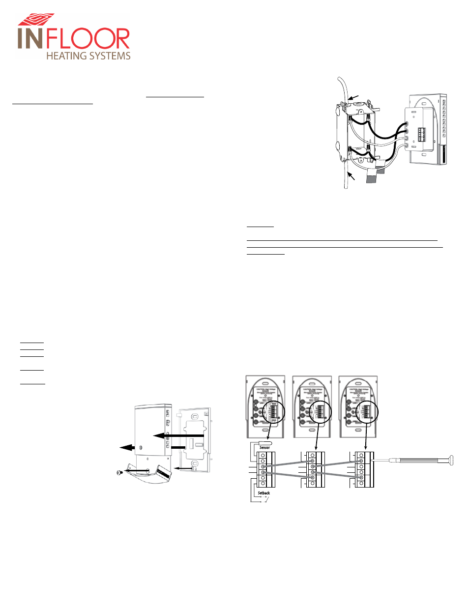
Connect Signal Wires From Thermostat
1. Pull 2-conductor wire, size 18- to 24-gage, through the wall from the
Infloor thermostat into this electrical box.
2. Connect the wire ends into the “RELIN” terminals(2 and 5) and tighten the
screws (observe polarity). See diagram below.
Connect Signal Wires to Other Infloor
Relays
You may drive up to 10 Infloor
Relays with one master Infloor
thermostat.
1. Connect 2-conductor wire, size 18- to 24-gage, into the “RELOUT”
terminals(3 and 4) of the first Relay.
2. Pull this wire through the wall to the next Relay and connect to its “RELIN”
terminals(2 and 5).
3. Repeat this process for additional Infloor
Relays.
5. The circuit breaker in the main circuit panel should be 15 amps maximum
for a floor warming system totaling 12 amps or less. For larger systems up to
15 amps, use a 20 amp maximum circuit breaker. Never exceed 15 amps on
this thermostat..
6. Pull the power supply wiring into this box, leaving about 6 inches of wire.
7. Pull the power lead wires from your floor warming system up the wall, into
this box.
8. Mount the electrical box.
Master
Thermostat
Relay 1
Relay 2
Continued on back