Installing filtration system, Turn off water supply before starting – InSinkErator F-201 Filtration System User Manual
Page 3
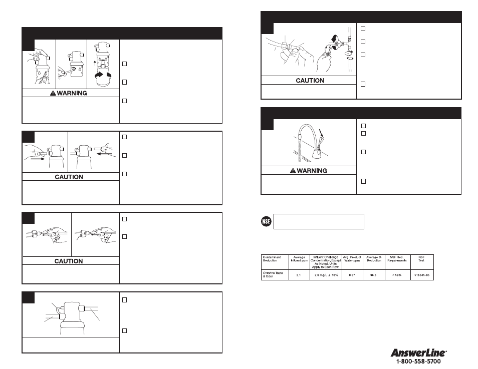
F-201R Cartridge (included with this system) Chemical & Mechanical Reduction Filter Specifications:
This cartridge provides mechanical and chemical reduction of dirt/rust, taste/odor and chlorine.
Filter Capacity: 500 gallons, depending on local water conditions. Note that while the testing was performed under
standard laboratory conditions, actual performance may vary. Do not use with water that is microbiologically unsafe or
of unknown quality without adequate disinfection before or after the system. For cold water use only. Systems must be
installed and operated in accordance with the Manufacturer’s recommended procedures and guidelines. See warranty
card for warranty. For service and parts, contact your local dealer or InSinkErator
®
directly at 1-800-558-5700.
Application guidelines/Water Supply Parameters for NSF Testing: Service flow of 0.75 gpm, community or
private well water supply, water pressure of 20-120 psi, water temperature of 33°F–100°F. Except as noted, all
testing performed at pH = 7.5 ± 0.5, Flow: 0.75 gpm, Pressure: 60 psi, Temp: 20°±3°C.
Contact an authorized InSinkErator service agent for repairs or replacement components.
Pressure: 20-120 psi
Temperature: 33º - 100ºF
Flow Rate: 0.75 gpm
Capacity: 500 gallons
Tested and Certified by NSF International against
NSF/ANSI Standard 42 in model F-201 for the reduction
of claims specified on the Performance Data Sheet.
Turn off water supply before starting.
Installation must comply with all state and local laws and regulations.
Property Damage: Do not extend the lines farther
than the 16" provided. Ensure tube(s) and “Y”
connnector are securely fit.
Personal Injury: Do not locate filter above an
outlet or other electrical device. Install head and
bracket so that connections require no stretching,
kinking or pinching of tubing.
It is normal for approximately 2 oz. of water
to discharge when filter is removed.
Property Damage: Tube runs need to form to the
cabinet’s contours to allow storage space with no
sharp bends. Tubes need clean, perpendicular,
burr-free cuts to ensure a true fit.
a
Determine length of tubing required,
then cut to length making sure the cut
is perpendicular and burr-free.
Insert a white 3/8" tube into inlet side
of filter head
until it stops. Press in
again to ensure a secure fit.
Insert the other white 3/8" tube into
outlet side of filter head
until it stops.
Press in again to ensure a secure fit.
Mark hole locations for filter head
and bracket in a spot that allows
for filter replacement.
Drill 1/8" starter holes and attach
bracket to wall with wood screws,
turning until snug.
Remove red filter cap, insert filter
cartridge into filter head and twist
clockwise until “LOCK” arrow on the
filter aligns with arrow on bracket.
To redirect filter replacement water
discharge, place 6" clear tube over
vent hole on the left side of filter head.
Note: 3/8" fitting is required to make
connection to water supply.
Connect remaining white 3/8" tube to
incoming water supply line. (See Step 2.)
c
Insert the copper tube(s) from the
dispenser into “Y” quick-connector
using the plug for hot-only models.
Connect the white 3/8" tube from the
right outlet on the filter head into the
quick-connect fitting until it stops.
Press in again to ensure a secure fit.
from water
supply line
to dispenser
To remove tube(s) or plug from quick-connector,
depress the release ring and gently pull away.
d
INSTALLING FILTRATION SYSTEM
b
From water
supply line
Discharge tube
To dispenser
Scalding Hazard: The faucet dispenses near-boiling
(212ºF) water which can instantly cause scalds or
burns. Use care when operating this appliance.
Property Damage: Join remaining tube
to cold water supply only.
Turn on the water supply.
Depress the dispenser’s HOT handle
and hold it until water flows from the
spout (approximately 1 to 2 minutes).
For the F-201 and F-201R, flush 2.25
gallons through filter before use
(approximately 3 minutes). For the
F-601R, flush 3 gallons through filter
before use (approximately 3 minutes).
Check all connections to ensure they
are tight and that there are no leaks.
Install a T-fitting
(not included)
onto the cold water supply line.
Install dedicated water control valve
with 3/8" compression fitting.
At the end of the white 3/8" tube
from the filter or quick-connector,
slide the supplied brass nut and
ferrule over the tube and then push
in the brass tube insert.
Insert the white 3/8" tube into the 3/8"
compression fitting and tighten.
FINAL WATER CONNECTION
TURN ON WATER & CONNECT POWER
Brass Nut
Ferrule
Brass
Insert
3/8"
Plastic
Tube
3
2
1
5
4
a
a
Screws provided are for use in wood
studs or cabinets only. Use wall anchors
(not supplied) for installation into drywall.
From filter or
water supply line
Plug
From filter or
water supply line
HC1100, HC2200,
HC2215
GN1100, GN2200, GN2215,
HC3300, H3300