Assembly of mig equipment – Kemppi Feed 420R User Manual
Page 9
Kempomig Feed 420R, 120R / 0429 – 9
©
COPYRIGHT
KEMPPI
OY
25 m/min 18 m/min
1
2
3
4
5
6
7
8
A001
JUMPER BLOCK
21
23
24
21
22
25
22
20
25
2.4.
ASSEMBLY OF MIG EQUIPMENT
Kempomig power source:
Read paragraph INSTALLATION in the operation instructions (1922430E) for the Kempomig-
power source in question.
Feed 420R and Feed 120R wire feeding equipment:
1. Mount the wire feeder onto the shaft which is on top of the power source. The shaft must have
plastic insulation / bear bushing.
2. Mount control cable of interconnection cable and welding current cable to connectors on the
rear wall of Feed 420R. Select the MIG gun´s polarity (+ or –) according to welding wire you
are using.
3. Mount the MIG gun to EURO connector on the front wall of the Feed 120R.
Use guide tubes and contact tips according to manufacturer´s operation instructions.
Accessories which are too tight or otherwise unsuitable for the wire type used will cause wire
feed disturbances.
4. If you mount the Feed 420R onto boom, see that the wire feeder unit´s chassis is without
galvanic contact to boom.
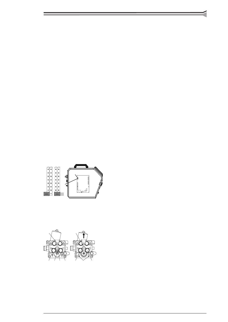
5. Max. wire feed speed
When the unit is delivered the max. wire feed speed is 18 m/min, which is enough for most
welding works. If you need a higher speed, you can increase the max. wire feed speed to
25 m/min by replacing the gear wheel on motor shaft to a bigger one as well as through change
of jumper on the control card. The big gear wheel (D40) belongs to delivery kit of the Feed
120R.
When necessary speed is changed according to following:
– Open side plate and move JUMPER BLOCK´s fi rst coding piece on control card A001 to
point 25m/min.
– Open tightening lever (20). Remove lower feed rolls (21). Release screw (23) and its washer.
Remove gear wheel D28 (24) from motor shaft.
– Loosen screws (25) (3 pc) 1 twist. Mount the D40 gear wheel onto motor shaft. Screw the
screw (23) with its washer back.
– Put feed rolls (21) back to their axles, however don´t fasten yet fastening screws of the feed
rolls (22).
– Lift the motor so that the tooth gap between gear wheel and both lower feed rolls is approx.
0,2 mm.