Using your router table, Reducing rings, Jointing – Kreg PRS2100 Precision Benchtop Router Table User Manual
Page 9
Using Your Router Table
8.
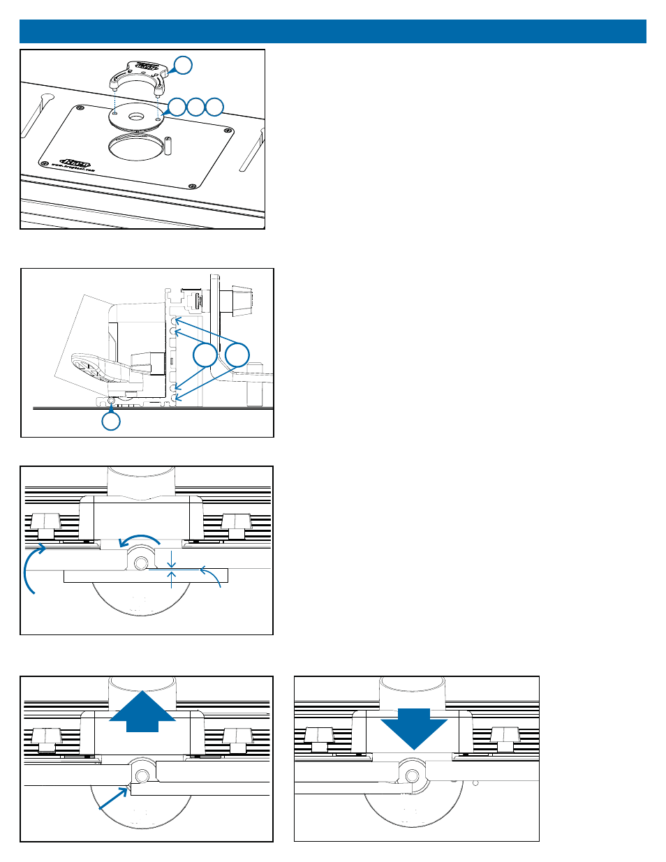
Reducing Rings
The Kreg Precision Insert Plate includes three reducing rings (#38, #39,
#40)
for fl exibility in matching the size of the insert-plate opening to the
diameter of the router bit in use. The ring with the rabbeted opening
accepts standard Porter-Cable-style guide bushings, allowing you to
use your router table for pattern routing. A set of fi ve additional reducing
rings is available from your Kreg dealer (Item #PRS3050). It includes
one blank disk for making a zero-clearance ring. To install a reducing
ring, simply drop it into the insert-plate opening and turn it by hand until it
drops fl ush with the plate surface. Insert the pegs at the ends of the arms
on the ring wrench (#41) into the mating holes in the reducer ring and
rotate the ring counterclockwise. Rotation of about ⅜" is suffi cient to lock
the ring in place. To remove the ring, turn the wrench clockwise and lift
the ring out of the opening.
40
Jointing
39
The independently adjustable fence faces on the Kreg Precision Router
Table Fence allow you to use your router table as a vertical jointer. To
set up for jointing, remove the two jointing rods (37) stored in the fence
extrusion. Loosen the knobs securing the outfeed fence face. There
are two sets of round channels in the fence extrusion behind the fence
faces, which allow you to offset the outfeed fence face
1
⁄
16
" or
1
⁄
32
" from
the infeed fence face. For a
1
⁄
16
" offset, slide the rods into the shallower
recesses. For a
1
⁄
32
" offset, slide the rods into the deeper recesses.
(When jointing, usually it is best to make light passes, so you’ll probably
use the
1
⁄
32
" offset more frequently than the
1
⁄
16
" offset.) With the rods in
place, tighten the outfeed fence-face knobs.
Install a straight bit in the router. Placing a steel rule or a piece of wood
with a straight edge against the outfeed fence face, position the fence
so the bit just grazes the rule or the piece of wood. Any straight bit can
be used for jointing, but a fl ush-trim bit is the easiest to set up. Because
the bit guide bearing is the same diameter as the cutter, you can align
the outfeed fence face with the bearing. An up-cut spiral bit produces an
almost chatter-free surface, but is a little more diffi cult to align with the
fence face.
Use a scrap piece of wood to test the setup. If, as you feed the scrap
past the bit, it runs into the leading end of the outfeed fence face, the
fence is too far forward and you’re not removing enough material. Move
the fence back a little. If you get snipe at the trailing edge of the scrap,
the fence is too far back, and you’re removing too much material. Move
the fence forward.
Bit rotation
infeed
outfeed
Jointing
rod
Jointing
offset
Move fence back
Workpiece
hits outfeed
fence face
Move fence forward
41
38
37
1
⁄
32
"
1
⁄
16
"