Controls and indicators – LD Systems MS 828 User Manual
Page 7
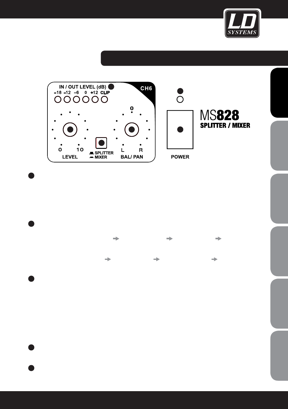
CONTROLS AND INDICATORS:
7
BAL/PAN CH1 - CH6
Channel in SPLITTER mode: Balance control for the signals at the stereo input. Adjustment of the balance in
volume between the left and right input signal (MAIN IN). The two signals are merged into a mono signal that
is present at the output of each channel.
Channel in MIXER mode: Panorama control for the signal at the individual input channel 1 - 6. Setting of the
position in the stereo mix of the MAIN OUT.
8
SPLITTER- / MIXER
Switch not depressed: Respective channel 1 - 6 is used as a splitter channel.
Signal flow: MAIN IN LEFT/RIGHT (12)
MAIN INPUT LEVEL (1)
CHANNEL LEVEL (6)
CHANNEL OUTPUT
(15)
Switch depressed: Respective channel 1 - 6 is used as a mixer channel.
Signal flow: CHANNEL INPUT (14)
CHANNEL LEVEL (6)
MAIN OUTPUT LEVEL (2)
MAIN OUT LEFT/
RIGHT (13)
9
IN / OUT LEVEL
Channel in SPLITTER mode: 6-segment LED level meter for the output level of the respective channel
1 - 6. Brief flashing of the red CLIP LED when peaks occur in the connected signal is not critical. Permanent
illumination of the CLIP LED should be avoided by reducing the volume at the MAIN INPUT LEVEL control and
or at the LEVEL control in the channel.
Channel in MIXER mode: 6-segment LED level meter for the input level of the respective channel 1 - 6. Brief
flashing of the red CLIP LED when peaks occur in the connected signal is not critical. Permanent illumination
of the CLIP LED should be avoided by reducing the volume of the source device and/or the volume at the
LEVEL control in the channel.
10
POWER
On / off switch
11
POWER LED
Lights up once the system is properly connected to the power mains and switched on.
7
IT
ALIANO
POLSKI
ESP
AÑOL
FRANCAIS
FRANCAIS
FRANCAIS
FRANCAIS
FRANCAIS
DEUTSCH
ENGLISH
6
8
7
9
10
11