Legrand SC600IV User Manual
Integrated 5-scene preset dimming system
Important: Retain These Instructions For The End User.
DO NOT THROW AWAY!
For Use with Models: SCMC5, SC600, SCELV600, SCFB600,
SCDH15, SCR, SCIR, SCMCK
DESCRIPTION
Pass & Seymour Scene Control products are a
revolutionary system of advanced digital wallbox
dimmers for economical and flexible multi-scene, multi-
channel control. They provide flexible 5-scene preset
dimming control of up to 30 devices as well as 12
adjustable fade rates up to one hour that are
programmable by scene.
CAUTION
Be sure that power to the load being controlled has been
disconnected by removing fuse or turning circuit breaker
off. Installing these products with power on may expose
you to dangerous voltage and/or damage the device.
READ BEFORE BEGINNING INSTALLATION
1. All devices require a neutral connection. Each circuit feeding dimmers and
dimmed loads requires a separate neutral. Shared neutrals will result in
undesirable flashing of controlled loads.
2. Use Electronic Low Voltage dimmers to control only low-voltage fixtures
that have electronic, solid-state transformers or regular incandescent loads.
3. Use Fluorescent Ballast Dimmers to control Advance Mark X
®
Dimmable
Electronic Ballast.
4. Dimmers may be fed individually or in groups, regardless of phase.
5. Masters draw approximately one watt and may be fed from any circuit.
Multiple masters may be inter-connected. The total number of dimmers and
masters are not to exceed 30. An unlimited number of channel remotes
(SCR) may be used.
6. Line voltage must not be supplied by a GFI breaker.
INSTALLATION INSTRUCTIONS – DIMMERS
CAUTION: Be Sure that power is disconnected to avoid damage to unit and
shock hazard to installer.
1. If you are replacing an existing device with a Dimmer or Remote:
A. Remove faceplate from existing device.
B. Unscrew and pull device out of wallbox.
C. Disconnect wires from device. Identify and mark the "hot", "load" and
traveler wires connected to the device.
2. Be sure Dimmer is in "System Off" position by firmly pressing bottom of
device until it snaps into place and the "System Off" label at the top of
device is exposed.
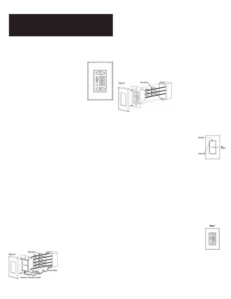
3. Connect the Dimmer wires to the Wallbox wires as follows:
A. Black to Hot (120V AC Source)
B. White to Neutral*
C. Red to Load (Light Fixture)
D. Yellow to Remote (SCR). Cap yellow if SCR is not used.
E. Purple to Network Connection (Line Voltage Class 1)**
4. Be sure the Ground wire (bare stranded) is connected to earth ground.
Note: Miswiring or failure to connect ground may result in improper
operation of the device.
5. Ensure all wire connectors are tight and completely cover copper wire,
(except ground).
6. Install device into wallbox, making sure that all wires are neatly installed
into wallbox. Using mounting screws provided, secure device into wallbox.
7. Install faceplate.
*
The White wire must be connected to the
neutral wire in the wallbox. Failure to
connect the White wire to the neutral will
result in improper operation.
**
Link all devices using one line voltage
wire connected between each Purple
wire. Connected devices will operate as
a system.
INSTALLATION INSTRUCTIONS – MASTERS (SCMC5)
1. Caution: Be sure that power is disconnected to avoid damage to unit and
shock hazard to installer.
2. Connect Master wires to the Wallbox wires as follows (Figure B):
A. Black to Hot (120V AC Source)
B. White to Neutral*
C. Purple to Network Connection (Line Voltage Class 1)**
3. Ensure all wire connectors are tight and completely cover copper wire.
4. Install device into wallbox, making sure that all wires are neatly installed
into wallbox. Using mounting screws provided, secure Master into wallbox.
5. Install faceplate.
*
The White wire must be connected
to the neutral wire in the wallbox.
Failure to connect the White wire to
the neutral will result in improper
operation.
**
Link all devices using one line
voltage wire connected between
each Purple wire. Connected
devices will operate as a system.
DIMMER OPERATING INSTRUCTIONS
1. To turn light on to preset level tap top of rocker. The dimmer will fade up
at the 1.5 second rate.
2. A second tap of the rocker fades the dimmer to full brightness.
3. To adjust the light level, press and hold top or bottom
of rocker until desired light level is reached, and then
release. Ramping will be at the 3 second rate.
4. To turn lights off, tap the bottom of the rocker. The
dimmer will fade at the 3 second fade rate.
5. To quickly return to the preset level when light is on,
quickly tap OFF and then ON. The lights will then
adjust to the preset level.
6. To bypass the fade rate and turn the lights to full ON or OFF, double tap
the dimmer for ON or OFF.
7. If the master is in the OFF scene, the master ON button will illuminate
when any dimmer is turned on.
8. To change the preset level of the current scene:
• Press and hold the rocker until lights reach the desired level then release
• Press the set button to save the preset in memory
LEDs on the Dimmers indicate status:
1. Red LED is on when Dimmer is off to locate Dimmer when room is dark.
2. As many as 3 green LEDs may be illuminated at any given time. The bright
green LED indicates the current level of the dimmer. The medium green
LED indicates the preset level of the current scene. The dim green LED
indicates the preset level of the ON scene.
PROGRAMMING AND OPERATING THE SCENE MASTER
After you have completed installation of all of the devices and have energized
the system, programming of each scene can be performed. Programming is
as simple as 1, 2, 3!
1. Tap the preset button (ON, A – D) on the Master Controller
that you wish to program.
2. Adjust each Dimmer to the desired intensity.
3. Press the Set button on each device (See step 8 in prior
section) after all devices have been adjusted.
Repeat Steps 1-3 until all scenes have been programmed.
* Note: Dimmers cannot be programmed off for the
“ON” preset.
Integrated 5-Scene Preset Dimming System
INSTALLATION & OPERATING INSTRUCTIONS
Part No. 340542 Rev. B
85-1209