Legrand 881AMD8TC User Manual
Page 6
6
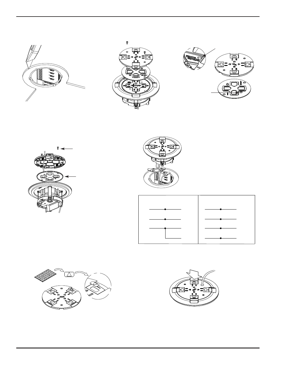
Pass-through
Knock Out
Cut Slot in Gasket for
cable pass-through
Slide Mounting Screw
(2) #6-32
Align Gasket over
Flange and press
bead into Flange
CAUTION: Gasket must be set in
place to provide scrub
water seal. Do not
over-tighten cover
mounting screws.
2. Remove the slide cover and gasket to
facilitate the routing of the
communication cables.
3. For communication cable pass-through,
remove the egress knockout(s) located
on the underside of the cover.
4. Pull communication cables through box. Route one of the
cables around the receptacle for cable egress opposite the
communication compartment in the floor box. Reattach
slide cover with (2) #6 screws. Pass through cabling must
pass through internal gasket and slide cover.
899CTC COVER INSTALLATION:
5. Connect receptacle leads to circuit conductors with
twist-on wire connector or other approved methods.
See schematic below.
CAUTION: Receptacle mounting means not
grounded. Grounding wire
connection required. For isolated
ground wiring, connect ground
leads to a separate isolated
grounding conductor (see NEC
250-146(d)).
WHITE or NEUTRAL
from branch circuit
WHITE
from slide cover receptacle
BLACK or HOT
from branch circuit
BLACK
from slide cover receptacle
GREEN (jumper wire)
from cover adapter ring
GREEN
from slide cover receptacle
CONVENTIONAL WIRING SCHEMATIC
WHITE or NEUTRAL
from branch circuit
WHITE
from slide cover receptacle
BLACK or HOT
from branch circuit
BLACK
from slide cover receptacle
GREEN (jumper wire)
from cover adapter ring
ISOLATED GROUND
from branch circuit
GREEN
from slide cover receptacle
ISOLATED GROUND WIRING SCHEMATIC
GREEN or GROUND
from branch circuit
SYSTEM GROUND
GREEN or GROUND
from branch circuit
SYSTEM GROUND
6. If circuit is connected to an isolated ground, apply
IG Icon on receptacle slide as shown.
CAUTION: Receptacle supplied with this activation is not
suitable for direct field wiring. Contact manufacturer
for replacement. Field modifications will void UL
Listing. Replacement receptacle is limited to this
manufacturer’s catalog No. RC9REC.
NOTE: The orange triangle shall only be placed on
devices that are wired for isolated ground.
See NEC 250-146(d).
7. Orient the open side of the cover adapter with the divided
side of the box and push into place – No glue required!
1. Cut a 6 1/2" [165mm] circular
concentric opening in the floor
covering.