Legrand RW3U603 User Manual
Legrand Hardware
Syracuse, NY 13221
RW3U603
Multi-way
Wall Switch
Vacancy Sensor
with Manual ON/OFF
In
sta
lla
tio
n I
ns
tru
cti
on
s
Please read all instructions before installing
DESCRIPTION AND OPERATION
RW3U603 Multi-way Wall Switch Vacancy Sensors are designed to replace
standard single pole and multi-way (3-way, 4-way) switches. They are ideal for
any room with multiple entries such as living and dining rooms, family rooms,
bedrooms, bathrooms, hallways, and any other indoor space where vacancy
sensor-based control with manual ON/OFF capability are desirable.
Like standard switches, you can press the ON/OFF button to turn the light
or fan (controlled load) ON and OFF. Unlike standard switches, the RW3U603
automatically turns OFF the controlled load after the coverage area has been
vacant for a period of time (Time Delay). If motion is detected within 30 seconds
after it automatically turns OFF, the RW3U603 automatically turns the load back
ON.
The RW3U603 can be wired with up to three additional RW3U603s for multi-
way Manual ON/OFF of one or several loads (up to one load connected to each
RW3U603). It can also be wired to up to four TM870STM single pole momentary
wall switches for multi-way Manual-ON/OFF Automatic-OFF control of one load.
Lighted Switch
To help you locate the RW3U603 in a dark room, the green LED illuminates the
ON/OFF button while the controlled load is OFF. When the controlled load is ON,
the LED is OFF.
Time Delay
The RW3U603 keeps the load ON until no motion is detected by any of the related
RW3U603s for the time delay period. The time delay can be selected by the user
during set up. It can be adjusted to any of these fixed values:15 seconds/
5 minutes/15 minutes/30 minutes. We recommend that the time delay be the
same in all sensors related to the same load. This makes it easier to understand
the multi-way control operation as well as trouble shooting. For additional
information on how to adjust it, please read the SENSOR ADJUSTMENT section
of this installation manual.
SPECIFICATIONS
Voltage ............................................................................. 120VAC, 60Hz
Load (Single Pole Circuit)
Incandescent or fluorescent ........................................... 0-600 Watts
Fan motor ................................................................................ 1/6 hp
Time Delay Adjustment .........................15 sec., 5 min., 15 min., 30 min.
Environment .................................................Residential Indoor use only
Operating Temperature .............................. 32° to 131°F (0° to 55°C)
Humidity ..................................................... 95% RH, non-condensing
Tools Needed
Insulated Screwdriver
Wire Strippers
Call 800.223.4185 for Technical Support
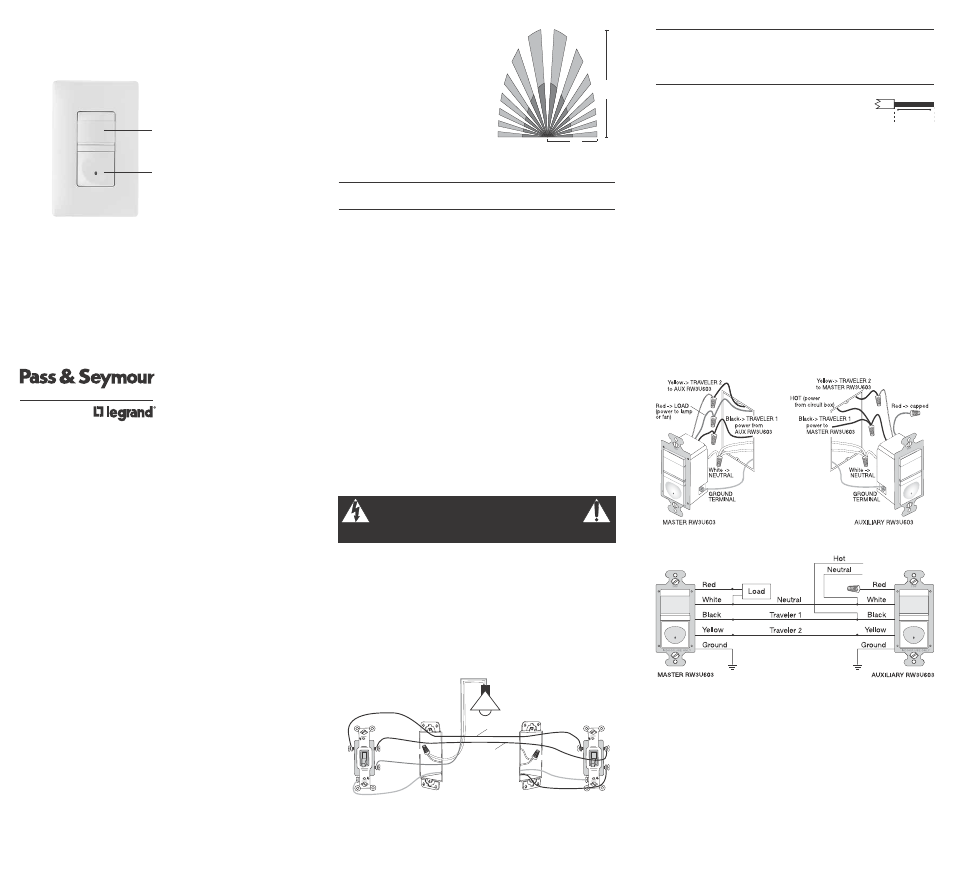
Coverage Area
The RW3U603 has a maximum coverage
range of 180 degrees and a coverage area
of 600 square feet (56 square meters). The
sensor must have a clear and unobstructed
view of the coverage area. Objects blocking
the sensor’s lens may prevent detection
thereby causing the light to turn OFF even
though someone is in the area.
Windows, glass doors, and other transparent barriers will
obstruct the sensor’s view and prevent detection.
INSTALLATION & WIRING
These instructions describe only the 3-way circuit applications. For information
about other applications, consult technical support.
WARNING
Disconnect power to the wall switch box by turning OFF
the circuit breaker or removing the fuse for the circuit before
installing the RW3U603, replacing lamps, or doing any electrical work.
1. Prepare the switch box.
After the power is turned OFF at the circuit breaker box, remove the existing
wall plate and mounting screws. Pull the old switch out from the wall box.
2. Identify the type of circuit.
You may connect the RW3U603 to a single pole or multi-way circuit. If you are
unable to clearly identify some or all of the wires mentioned in this manual,
you should consult with a qualified electrician.
In a 3-way circuit (see Fig. 2), two traveler wires connect to both switches.
Another wire provides power from the circuit box to one of the switches. A wire
connects from one switch to the load. A ground wire may also be connected to
a ground terminal on the old switches. A neutral wire should also be present in
both wall boxes.
NEUTRAL
GROUND
LOAD/Common
(power to lamp)
NEUTRAL
GROUND
HOT/Common
(power from circuit box)
TRAVELER
TRAVELER
Lamp/load
MASTER SWITCH
AUXILIARY SWITCH
Fig. 2: Typical 3-Way Switch Wiring
www.passandseymour.com
Lens
Lighted Switch
ON/OFF Button
25'
(7.6m)
12'
(3.7m)
Fig. 1: Sensor Coverage Area
CAUTION
For your safety: Connecting a proper ground to the sensor
provides protection against electrical shock in the event of certain
fault conditions. If a proper ground is not available, consult with
a qualified electrician before continuing installation.
3. Prepare the Wires.
Tag the wires currently connected to the existing switch
so that they can be identified later. Disconnect the wires.
Make sure the insulation is stripped off of the wires to
expose their copper cores to the length indicated by the
“Strip Gage,” in Fig. 3. (approx. 1/2 inch).
4. Wire the sensor.
Twist the existing wires together with the wire leads on the RW3U603 sensor(s)
as indicated in either step 4a or 4b. Cap wires securely using wire nuts.
4a. Wiring two RW3U603s in a 3-way configuration
• Connect the green or non-insulated (copper) GROUND wire from the circuit to
the green terminal on each RW3U603.
• Connect the NEUTRAL wire from the circuit and from the lamp (LOAD) to the
white wire on the master RW3U603.
The term “master” designates the RW3U603 that connects to the load.
• Connect the NEUTRAL wire from the circuit in the other wiring box to the white
wire on the auxiliary RW3U603.
• Connect the power wire from the circuit box (HOT) to the black wire on the
auxiliary RW3U603 and to the TRAVELER 1 wire.
• Connect the TRAVELER 1 wire from the black wire of the auxiliary RW3U603 to
the black wire of the master RW3U603.
• Connect the lamp power (LOAD) to the red wire on the master RW3U603.
• Cap the red wire on the auxiliary RW3U603.
• Connect the TRAVELER 2 wire coming from the yellow wire of another
RW3U603 to the yellow wire of the RW3U603 that you are wiring.
Fig. 4: Step 4a, Sensor orientation, wire connections and wall box assembly
Fig. 5: Step 4a, Reference wiring diagram
Call 800.223.4185 for Technical Support
Strip Gage
1/2"
12.7 mm
Fig. 3: Wire
Stripping