Legrand RW3U603 User Manual
Page 2
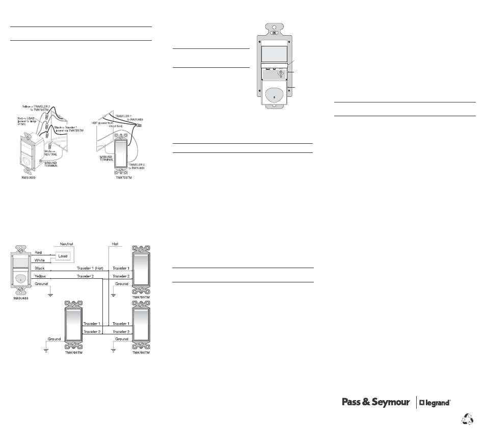
4b. Wiring one RW3U603 and one TM870STM single pole momentary
switch for multi-way Manual-ON/OFF single load control.
IMPORTANT: The RW3U603 must be installed in the
wiring wall box that connects to the load.
• Connect the green or non-insulated (copper) GROUND wire in each wiring box
to the green terminal on each RW3U603 and TM870STM.
• Connect the NEUTRAL wire from the circuit and from the lamp (LOAD) to the
white wire on the RW3U603.
• Connect the power wire from the circuit box (HOT) to one terminal of the
TM870STM single pole momentary wall switch and to the TRAVELER 1 wire.
• Connect the TRAVELER 1 wire coming from the TM870STM wiring box to the
black wire of the RW3U603.
• Connect the lamp power (LOAD) to the red wire on the RW3U603.
• Connect the TRAVELER 2 wire to the other side of the TM870STM single pole
momentary wall switch and to the yellow wire of the RW3U603.
Fig. 6: Step 4b, Sensor orientation and wire connections for 3-way operation
with an TM870STM momentary wall switch
To wire up to four TM870STM single pole momentary wall switches to one
RW3U603, wire them in parallel as shown in the following wiring diagram.
Fig. 7: Step 4b, Reference wiring diagram for multi-way operation with
TM870STM momentary wall switches (4 maximum)
5. Put all the new switches into their wall boxes.
Position the RW3U603 switch(es) with the lens above the ON/OFF button (lens
at top, ON/OFF button at bottom). Use the captive screws on the mounting
strap to secure the switches to their wall boxes.
6. Restore power to the circuit.
Turn on the breaker or replace the fuse.
7. Make any necessary adjustments.
See the SENSOR ADJUSTMENT section for information.
8. Attach the new cover plates.
Secure them with the screws provided.
www.passandseymour.com
Call 800.223.4185 for Technical Support
SENSOR ADjUSTMENT
To adjust the RW3U603, you use a control
located under the ON/OFF button. The wall
switch cover plate must be removed to gain
access to the time delay adjustment dial
under the ON/OFF button.
For multi-way operation, the Time
Delay should be the same in all
sensors related to the same load.
1. Firmly grasp the side edges of the
Lock Bar and gently pull it away from
the switch face until it clicks. Do NOT
attempt to pull the Lock Bar off of the
switch!
2. Firmly grasp the side edges of the
ON/OFF button. Slide the button
downward approximately 1/2 inch
to expose the adjustment dial.
Adjusting the Time Delay
Turn the dial counter-clockwise to reduce the amount of time the lights will
remain ON after the last motion detection (minimum = 15 seconds). Turn it
clockwise to increase the time delay (maximum = 30 minutes). You can only
select the following values: 15 seconds/5 minutes/15 minutes/30 minutes.
Warning: Do not overturn the Time Delay adjustment dial!
TEST MODE
To test the detection coverage:
1. Press and hold the ON/OFF button. After 10 seconds the lighted switch turns
off. The load turns ON if it was not already ON. The sensor is now in a TEST
mode that lasts 5 minutes. (You can end the TEST mode sooner by pressing the
ON/OFF button for another 10 seconds).
During the TEST mode, the controlled load turns ON for 5 seconds each
time the sensor that initiated the TEST mode detects occupancy.
2. Move out of the coverage area or stand very still. The controlled load turns OFF
after 5 seconds if no motion is detected.
3. Move into the coverage area for the unit that initiated the TEST mode. The
controlled load turns ON for 5 seconds each time the sensor detects motion.
After 5 seconds expire without motion detection, the load turns OFF. The
controlled load turns ON automatically with the next motion detection and
stays ON for 5 seconds.
4. Repeat as necessary to ensure that the desired coverage areas are within
detection range.
You can do this test for each RW3U603 in your multi-way configuration. So
that you can determine the actual coverage area for each multi-way switch
individually, only the RW3U603 that is in TEST mode will control the load.
TOP
Lock Bar
Time Delay
Adjustment
Dial
Slide down
ON/OFF
Buttons
09560r1
Suggested time delays
Bath or Ded room: 30: min.
Half or Stairway: 5-15 min
30
M
in
.
S
ec
.
15
Min.
5
Min.
15
Fig. 8: Sensor Adjustment Control
WARRANTy INFORMATION
Pass & Seymour/Legrand warranties its products to be free of defects in
materials and workmanship for a period of five (5) years. There are no obligations
or liabilities on the part of Pass & Seymour/Legrand for consequential damages
arising out of, or in connection with, the use or performance of this product or
other indirect damages with respect to loss of property, revenue or profit, or cost
of removal, installation or reinstallation.
Please
Recycle
TROUBLESHOOTING
Lighted switch is OFF, no load response to ON/OFF button press:
• Make certain that the circuit breaker is on and functioning.
Lighted switch is ON, no load response to ON/OFF button press:
• Check the light bulb and/or motor switch on the fan mechanism.
Load will not turn OFF automatically:
• Press ON/OFF button. If the controlled load turns OFF, go to next step.
• The time delay can be set from 15 seconds to 30 minutes. Check the time delay
setting for each RW3U603 in your multi-way configuration. Ensure that all
RW3U603s have the same time delay setting.
• Ensure that there is no movement within the coverage area for all the sensors
related to the load for the set time delay. Hot air currents and heat radiant
devices can cause false detection. Make sure the sensor is at least 6 feet
(2 meters) away from devices that are a significant heat source (e.g., heater,
heater vent, high wattage light bulb).
If load does not respond properly after following troubleshooting, turn OFF
power to the circuit then check wire connections or call technical support.
P.O. Box 4822, Syracuse, NY 13221-4822
Technical Support: 800.223.4185
www.passandseymour.com
340887 11533