Basic connections, English, Connecting audio components – Marantz SR5023 User Manual
Page 12: Connecting speakers, Connecting speaker wire, Connecting a subwoofer, Loosen the knob by turning it counterclockwise
8
BASIC
CONNECTIONS
BASIC
OPERA
TION
ADV
ANCED
CONNECTION
ADV
ANCED
OPERA
TION
TROUBLESHOOTING
OTHERS
BASIC
CONNECTIONS
NAMES AND
FUNCTIONS
ENGLISH
BASIC CONNECTIONS
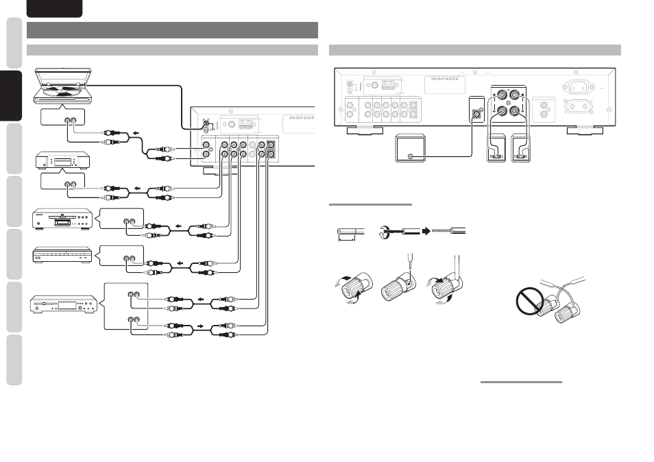
CONNECTING AUDIO COMPONENTS
PHONO
PHONO
R
R
L
L
PHONO GND
PHONO GND
CD
CD
DVD
DVD
DSS
DSS
AUX
AUX
RECORDER 1
RECORDER 1
R
R
L
L
R
R
L
L
IN
IN
IN
IN
IN
IN
IN
IN
IN
IN
IN
IN
OUT
OUT
(CD-R)
(CD-R)
MODEL NO. SR50
MODEL NO. SR5023
GND
GND AM
AM
FM
FM (
(75
75
Ω
Ω))
ANTENNA
ANTENNA
L R
PHONO
OUT
L R
ANALOG
OUT
L R
ANALOG
OUT
L R
ANALOG
IN
L R
AUDIO
OUT
L R
AUDIO
OUT
L
R
L
R
L
R
L
R
L
R
L
R
L
R
L
R
L
R
L
R
L
R
L
R
CD player
CD recorder
Turn table
DVD player
Satellite tuner
Caution:
• Do not connect this unit and other components to mains power until all connections between components have been
completed.
Notes:
• Insert all plugs and connectors securely. Incomplete connections may make noise.
• Be sure to connect the left and right channels properly.
Red connectors are for the R (right) channel, and white connectors are for the L (left) channel.
• Be sure to connect input and output properly.
• Refer to the instructions for each component that is connected to this unit.
• Do not bind audio/video connection cables with power cords and speaker cables this will result in generating a hum
or other noise.
CONNECTING SPEAKERS
PHONO
PHONO
R
R
L
L
AC IN
AC IN
SWITCHED
SWITCHED
150W 0.65A MAX.
150W 0.65A MAX.
AC OUTLET
AC OUTLET
230V 50/60Hz
230V 50/60Hz
PHONO GND
PHONO GND
CD
CD
DVD
DVD
DSS
DSS
AUX
AUX
RECORDER 1
RECORDER 1
R
R
L
L
R
R
L
L
IN
IN
IN
IN
IN
IN
IN
IN
IN
IN
IN
IN
OUT
OUT
(CD-R)
(CD-R)
SUB WOOFER
SUB WOOFER
PRE OUT
PRE OUT
L
L
R
R
SPEAKERS IMPEDANCE : 8-16 OHMS
SPEAKERS IMPEDANCE : 8-16 OHMS
SPEAKER SYSTEMS
SPEAKER SYSTEMS
N
N
MODEL NO. SR5023
MODEL NO. SR5023
GND
GND AM
AM
FM
FM (
(75
75
Ω
Ω))
ANTENNA
ANTENNA
REMOTE CONTROL
REMOTE CONTROL
IN
IN
OUT
OUT
Right
Left
Powered
subwoofer
CONNECTING SPEAKER WIRE
1.
2.
3.
4.
5.
10 mm
(3/8inch)
1.
Strip away approx. 10 mm (3/8inch) of wire
insulation.
2.
Twist the bared wire ends tight, to prevent short
circuits.
3.
Loosen the knob by turning it counterclockwise.
4.
Insert the bare part of the wire into the hole in
side of each terminal.
5.
Tighten the knob by turning it clockwise to
secure the wire.
Caution:
• Be sure to use speakers with the specifi ed impedance
as shown on the rear panel of this unit.
• To prevent damage to circuitry, do not let the bare
speaker wires touch each other and do not let them
touch any metal part of this unit.
• Do not touch the speaker terminals when the power
is on. It may cause you to receive an electric shocks.
• Do not connect more than one speaker cable to one
speaker terminal. Doing so may damage this unit.
Note:
Be sure to connect the positive and negative cables for
the speaker properly. If they are miss-connected, the
signal phase will be reversed and the signal quality
will be corrupted.
CONNECTING A SUBWOOFER
Use the PRE OUT SUBWOOFER jack to connect a
powered subwoofer (power amplifi er built in).