Spray system, System description – MEGA Corp. MTT-OPS-1 User Manual
Page 21
MTT-OPS-1
13 Nov 2013
SECTION 2
System Description
2-12
In-Line Stream Shaper
A performance enhancer that is
mounted between the water
cannon outlet and the selected
straight bore nozzle. The stream
shaper pathway is a honeycomb
style channel designed to
efficiently shape a water stream
to maximum water stream
distance.
Manual Adjustable Nozzle
Fog/Stream: A modified straight bore nozzle that
allows the operator to manually adjust selected
water stream patterns from fog to stream. Some
nozzles are configured for fire suppression foam
eduction.
Fan/Stream: A modified straight bore nozzle that
allows the operator to manually adjust selected
water stream patterns from flat fan to stream. The flat
fan pattern orientation is adjustable from horizontal
to vertical by reorienting the nozzle on the water
cannon.
Remote Adjustable Nozzle (Electric/Hydraulic)
A modified straight bore nozzle that allows the
operator to remotely adjust selected water stream
patterns from fog to stream from the cab control. The
nozzle inner or outer barrel is moved by an electric or
hydraulic actuator to obtain the fog or stream
pattern. Some nozzles are configured for fire
suppression foam eduction.
Fan/Stream
A modified straight bore nozzle that allows the
operator to remotely adjust selected water stream
patters from flat fan to stream from the cab control.
The nozzle inner or outer barrel is moved by an
electric actuator to obtain the fan or stream pattern.
The flat fan pattern orientation is adjustable from
horizontal to vertical by reorienting the nozzle on the
monitor.
SPRAY SYSTEM
The spray head system consists of 4, 6 or 8 hydraulic
or pneumatic actuated spray heads, cab controls,
solenoid control box assembly and hydraulic or
pneumatic hosing.
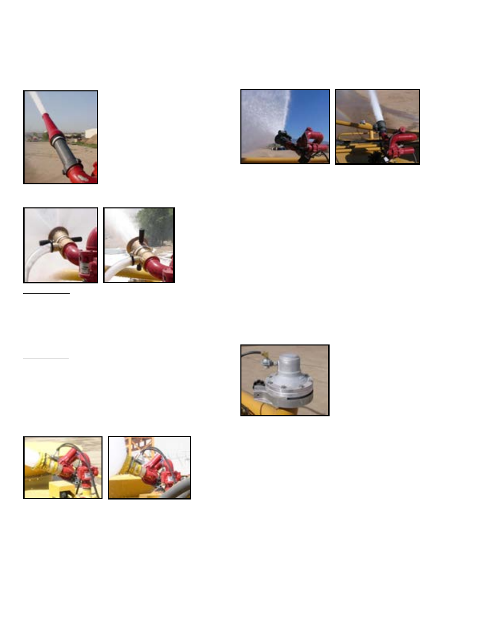
PNEUMATIC SPRAY HEAD
A two piece aluminum valve
body and adjustable ring
mounted to a water supply
header pipe. The upper
portion of the valve body is
an air chamber with a
diaphragm and guide disk
assembly attached to the bottom. The air chamber
receives pressurized air from the solenoid control box
as commanded by the cab control switch. When the
upper portion of the valve body is pressurized the
guide disk will seal the opening on the lower portion
of the valve and stop water flow.
When the cab control system is OFF and the water
pump is OFF the air chamber incorporates a spring
that will apply pressure to the guide disk assembly
and seal the opening on the lower portion of the
valve and stop flow. When air pressure is removed
from the upper portion of the valve body when the
water pump is ON and the cab control switch ON,
pressurized water from the header pipe will unseat
the guide disk and water will flow from the lower
portion of valve.