Dump bar, System description – MEGA Corp. MTT-OPS-1 User Manual
Page 22
MTT-OPS-1
13 Nov 2013
SECTION 2
System Description
2-13
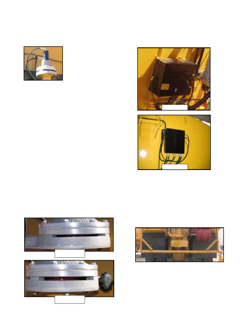
HYDRAULIC SPRAY HEAD
A two piece aluminum valve
body, hydraulic cylinder and
adjustable ring mounted to a
water supply header pipe. The
upper portion of the valve body
contains a hydraulic cylinder
that receives hydraulic pressure
from the system solenoid control box as commanded
by the cab control switch. When the hydraulic
cylinder on the upper portion of the valve body is
pressurized the cylinder extends to contact the guide
disk and seal the opening on the lower portion of the
valve and stop water flow. When the cab control
system is OFF and the water pump is OFF the upper
valve body incorporates a spring to apply pressure to
the guide disk to seal the opening on the lower
portion of the valve and stop flow. When the spray
head switch is turned on hydraulic pressure retracts
the hydraulic cylinder and pressurized water from the
header pipe will unseat the guide disk and water will
flow from the lower portion of valve.
Spray Head Adjustable Rings
The adjustable ring is used to control fan width and
water flow. The ring may be loosened and rotated to
expose more or less of the lower valve opening to
control water fan width from 15° to 90°. The ring also
may be used rotated to a 1/4” or 3/8” slot as shown in
figure 2-2 and 2-3 to increase or decrease overall
water flow. The greater the opening, the greater the
water flow.
SOLENOID CONTROL BOX
The control box assembly is mounted to the forward
bulkhead or top skin of the MTT. The assembly
contains pneumatic or hydraulic solenoid valves that
direct pneumatic or hydraulic pressure to the spray
head as commanded by the cab control box. The
solenoids receive pneumatic pressure from the
vehicle or hydraulic pressure from water pump oil
circuit and 24 VDC power from the cab control box.
DUMP BAR
A spray bar that contains several rows of 3/8” drain
holes to dispense water. A hydraulically operated BFV
controls the water supply to the dump bar. The BFV is
controlled electrically from the cab control box and is
actuated by a hydraulic cylinder. The actuators
receive hydraulic pressure from the solenoid control
box assembly. Dump bars can be either gravity or
pressure fed.
1/4” Opening
3/8” Opening
Pneumatic
Pneumatic