Daq-sync signals – Measurement Computing PCI-DAS6071 User Manual
Page 16
PCI-DAS6071 User's Guide
Functional Details
16
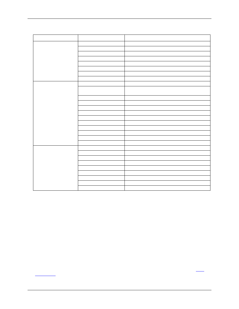
Auxiliary I/O Signals
I/O Type
Signal Name
Function
AUXIN<5:0> sources
(software selectable)
A/D CONVERT
External ADC Convert Strobe (default)
A/D TIMEBASE IN
External ADC Pacer Time Base
A/D START TRIGGER
ADC Start Trigger (default)
A/D STOP TRIGGER
ADC Stop Trigger (default)
A/D PACER GATE
External ADC Gate (default)
D/A START TRIGGER
DAC Trigger/Gate (default)
D/A UPDATE
DAC Update Strobe (default)
D/A TIMEBASE IN
External DAC Pacer Time Base
AUXOUT<2:0> sources
(software selectable)
STARTSCAN
A pulse indicating the start of conversion.
SSH
An active signal that terminates at the start of the last
conversion in a scan.
A/D STOP
Indicates the end of a scan
A/D CONVERT
ADC convert pulse (default)
SCANCLK
Delayed version of ADC convert (default)
CTR1 CLK
CTR1 clock source
D/A UPDATE
D/A update pulse (default)
CTR2 CLK
CTR2 clock source
A/D START TRIGGER
ADC Start Trigger Out
A/D STOP TRIGGER
ADC Stop Trigger Out
A/D PACER GATE
External ADC gate
D/A START TRIGGER
DAC Start Trigger Out
Default selections
summary
AUXIN0
A/D CONVERT
AUXIN1
A/D START TRIGGER
AUXIN2
A/D STOP TRIGGER
AUXIN3
D/A UPDATE
AUXIN4
D/A START TRIGGER
AUXIN5
A/D PACER GATE
AUXOUT0
D/A UPDATE
AUXOUT1
A/D CONVERT
AUXOUT2
SCANCLK
DAQ-Sync signals
The DAQ-Sync hardware provides the capability of triggering or clocking up to four slave boards from a master
board to synchronize data input and/or output.
The PCI-DAS6071 board provides the capability of inter-board synchronization between boards in the PCI-
DAS6000 family. There are five trigger/strobes and a synchronizing clock provided on a 14-pin header. The
following signals are available:
DS A/D START TRIGGER
DS A/D STOP TRIGGER
DS A/D CONVERT
DS D/A UPDATE
DS D/A START TRIGGER
SYNC CLK
Except for the SYNC CLK signal, the DAQ-Sync timing and control signals are a subset of the AUXIO signals
available at the 100-pin I/O connector. These versions of the signals are used for board-to-board
synchronization and have the same timing specifications as their I/O connector counterparts. Refer to "
" on page 18 for explanations of signals and timing.