Thermistor measurement accuracy: t0x-t3x – Measurement Computing USB-TEMP-AI User Manual
Page 23
USB-TEMP-AI User's Guide
Specifications
23
Note 11:
For accurate three wire compensation, the individual lead resistances connected to the ±Ix pins
must be of equal ohmic value. To ensure this, use connection leads of equal lengths.
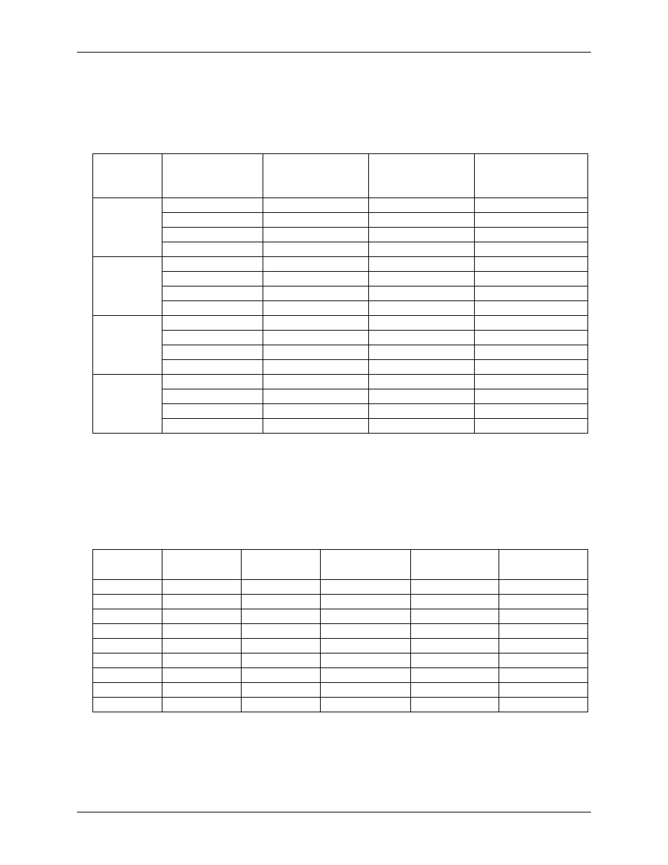
Thermistor measurement accuracy: T0x-T3x
Table 7. Thermistor measurement accuracy specifications, I
x+
= 10 µA. All specifications are (±)
Thermistor
Sensor
temperature range
Accuracy error
maximum
(°C)
Accuracy error
typical
(°C)
Tempco
(°C/°C)
2252 Ω
-40 °C
0.001
0.0007
0.001
0 °C
0.021
0.008
0.001
50 °C
0.263
0.130
0.001
120 °C
3.473
1.750
0.001
5000 Ω
-35 °C
0.001
0.0006
0.001
0 °C
0.009
0.004
0.001
50 °C
0.115
0.049
0.001
120 °C
1.535
0.658
0.001
10000 Ω
-25 °C
0.001
0.0005
0.001
0 °C
0.005
0.002
0.001
50 °C
0.060
0.028
0.001
120 °C
0.771
0.328
0.001
30000 Ω
-10 °C
0.001
0.0005
0.001
0 °C
0.002
0.001
0.001
50 °C
0.019
0.009
0.001
120 °C
0.267
0.128
0.001
Note 12:
Error shown does not include errors of the sensor itself. The sensor linearization is performed
using a Steinhart-Hart linearization algorithm. The accuracy and tempco specifications include the
accuracy of the Callendar-Van Dusen linearization algorithm. These specifications are for one year
while operation is between 15 °C and 35 °C. The specification does not include lead resistance errors
for 2-wire thermistor connections. Contact your sensor supplier for details on the actual sensor error
limitations. Total thermistor resistance on any given channel pair must not exceed 180 kΩ. Typical
resistance values at various temperatures for supported thermistors are shown in Table 8.
Table 8. Typical thermistor resistance measurement range
Temp °C
2252 Ω
thermistor
3000 Ω
thermistor
5 kΩ
thermistor
10 kΩ
thermistor
30 kΩ
thermistor
–40
76 kΩ
101 kΩ
168 kΩ
240 kΩ (Note 13)
885 kΩ (Note 13)
–35
55 kΩ
73 kΩ
121 kΩ
179 kΩ
649 kΩ (Note 13)
–30
40 kΩ
53 kΩ
88 kΩ
135 kΩ
481 kΩ (Note 13)
–25
29 kΩ
39 kΩ
65 kΩ
103 kΩ
360 kΩ (Note 13)
–20
22 kΩ
29 kΩ
49 kΩ
79 kΩ
271 kΩ (Note 13)
–15
16 kΩ
22 kΩ
36 kΩ
61 kΩ
206 kΩ (Note 13)
–10
12 kΩ
17 kΩ
28 kΩ
48 kΩ
158 kΩ
–5
9.5 kΩ
13 kΩ
21 kΩ
37 kΩ
122 kΩ
0
7.4 kΩ
9.8 kΩ
16 kΩ
29 kΩ
95 kΩ
Note 13:
Resistance values greater than 180 kΩ cannot be measured by the device in the thermistor mode.
The 180 k Ω resistance limit includes the total resistance across the current excitation (±Ix) pins, which
is the sum of the thermistor resistance and the lead resistances.
Note 14:
For accurate three wire compensation, the individual lead resistances connected to the ±Ix pins
must be of equal ohmic value. To ensure this, use connection leads of equal lengths.