Connectors, Dsub-25 connector pin assignments, Component layout – Meinberg DCF77C51 User Manual
Page 15: Usage of the current loop interface, Active output to passive input
Advertising
15
Connectors
Name
Type
Signal
Cable
Serial Interface
25 pin SUB-D
RS232
shielded data line
20mA
Pulse Outputs
pulse per second
pulse per minute
Antenna
BNC
77.5kHz
shielded coaxial line
(RG174/RG58)
Power Supply
230V /AC
power supply cord
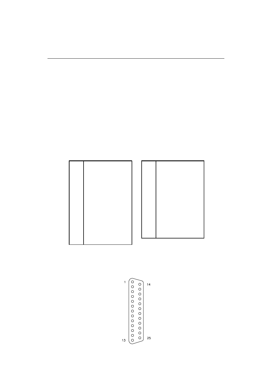
DSUB-25 Connector Pin Assignments
1
14
P_SEC out, collector
2
RxD in
15
P_SEC out, emitter
3
TxD out
16
P_MIN out, collector
4
RTS (connected with CTS)
17
P_MIN out, emitter
5
CTS (connected with RTS)
18
6
DSR (connected with DTR)
19
7
GND
20
DTR (connected with DSR)
8
P_SEC (RS232)
21
-act_in
9
-pass_in / +act_in
22
10
+pass_in
23
11
curr_loop +5V out
24
curr_loop -15V in
12
+pass_out
25
-act_out
13
-pass_out / +act_out
DB25 connector, female, front view
Advertising